Single-Domain SR-TE その10(On Demand Next-hop:ODN with L3VPN)

On Demand Next-hop:ODN with L3VPN が理解できたので自分のメモ用にアウトプットします。

1. On Demand Next-hop:ODN

ODNはSR-PolicyのInstance化を自動化するもので、指定の Prefix をオンデマンドに SR-TE に反映します。
今回は、Dynamic SR-TE を使ったODN(L3VPN)を検証します。
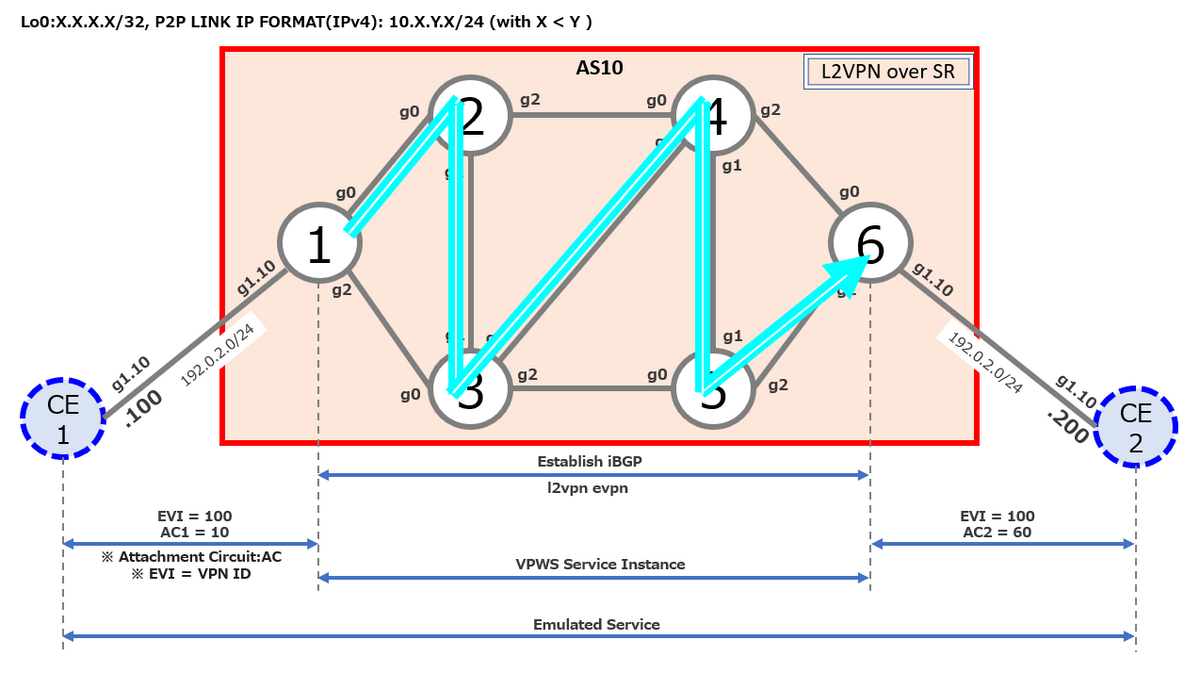
2. Topology

3. Config

◆h_N1

hostname h_N1
group CCIE-ISIS
 router isis '.*'
  is-type level-2-only
  address-family ipv4 unicast
   metric-style wide
   segment-routing mpls
  !
  interface 'Gi.*'
   point-to-point
   address-family ipv4 unicast
   !
  !
  interface 'Loopback .*'
   address-family ipv4 unicast
   !
  !
 !
end-group
!
vrf A
 rd 10:1
 address-family ipv4 unicast
  import route-target
   200:1
  !
  export route-target
   100:1
  !
 !
!
interface Loopback0
 ipv4 address 1.1.1.1 255.255.255.255
!
interface MgmtEth0/RP0/CPU0/0
 shutdown
!
interface GigabitEthernet0/0/0/0
 ipv4 address 10.1.2.1 255.255.255.0
!
interface GigabitEthernet0/0/0/1.20
 vrf A    
 ipv4 address 198.51.100.1 255.255.255.0
 encapsulation dot1q 20
!
interface GigabitEthernet0/0/0/2
 ipv4 address 10.1.3.1 255.255.255.0
!
interface GigabitEthernet0/0/0/3
 shutdown
!
interface GigabitEthernet0/0/0/4
 shutdown
!
route-policy PASS
  pass
end-policy
!
router isis 1
 apply-group CCIE-ISIS
 net 49.0001.0000.0000.0001.00
 distribute link-state level 2
 address-family ipv4 unicast
  mpls traffic-eng level-2-only
  mpls traffic-eng router-id Loopback0
 !
 interface Loopback0
  address-family ipv4 unicast
   prefix-sid index 1
  !
 !
 interface GigabitEthernet0/0/0/0
 !
 interface GigabitEthernet0/0/0/2
 !
!
router bgp 10
 bgp router-id 1.1.1.1
 address-family vpnv4 unicast
 !
 neighbor 6.6.6.6
  remote-as 10
  update-source Loopback0
  address-family vpnv4 unicast
  !
 !
 vrf A
  rd 10:1
  address-family ipv4 unicast
  !
  neighbor 198.51.100.100
   remote-as 100
   address-family ipv4 unicast
    route-policy PASS in
    route-policy PASS out
   !
  !
 !
!
mpls oam
!
segment-routing
 traffic-eng
  on-demand color 10
   dynamic
    metric
     type te
    !
   !
  !
  on-demand color 20
   dynamic
    metric
     type igp
    !
   !
  !
  on-demand color 30
   dynamic
    metric
     type latency
    !
   !
  !
  on-demand color 40
   dynamic
    metric
     type hopcount
    !
   !      
  !
 !
!
mpls label range table 0 1001001 1001999
end

◆h_N2

hostname h_N2
group CCIE-ISIS
 router isis '.*'
  is-type level-2-only
  address-family ipv4 unicast
   metric-style wide
   segment-routing mpls
  !
  interface 'Gi.*'
   point-to-point
   address-family ipv4 unicast
   !
  !
  interface 'Loopback .*'
   address-family ipv4 unicast
   !
  !
 !
end-group
!
interface Loopback0
 ipv4 address 2.2.2.2 255.255.255.255
!
interface MgmtEth0/RP0/CPU0/0
 shutdown
!
interface GigabitEthernet0/0/0/0
 ipv4 address 10.1.2.2 255.255.255.0
!
interface GigabitEthernet0/0/0/1
 ipv4 address 10.2.3.2 255.255.255.0
!
interface GigabitEthernet0/0/0/2
 ipv4 address 10.2.4.2 255.255.255.0
!
interface GigabitEthernet0/0/0/3
 shutdown
!
interface GigabitEthernet0/0/0/4
 shutdown
!
router isis 1
 apply-group CCIE-ISIS
 net 49.0001.0000.0000.0002.00
 address-family ipv4 unicast
  mpls traffic-eng level-2-only
  mpls traffic-eng router-id Loopback0
 !
 interface Loopback0
  address-family ipv4 unicast
   prefix-sid index 2
  !
 !
 interface GigabitEthernet0/0/0/0
 !
 interface GigabitEthernet0/0/0/1
 !
 interface GigabitEthernet0/0/0/2
  address-family ipv4 unicast
   metric 15
  !
 !
!
mpls oam
!
segment-routing
 traffic-eng
  interface GigabitEthernet0/0/0/2
   metric 15
  !       
 !
!
performance-measurement
 interface GigabitEthernet0/0/0/2
  delay-measurement
   advertise-delay 5
  !
 !
!
end

◆h_N3

hostname h_N3
group CCIE-ISIS
 router isis '.*'
  is-type level-2-only
  address-family ipv4 unicast
   metric-style wide
   segment-routing mpls
  !
  interface 'Gi.*'
   point-to-point
   address-family ipv4 unicast
   !
  !
  interface 'Loopback .*'
   address-family ipv4 unicast
   !
  !
 !
end-group
!
interface Loopback0
 ipv4 address 3.3.3.3 255.255.255.255
!
interface MgmtEth0/RP0/CPU0/0
 shutdown
!
interface GigabitEthernet0/0/0/0
 ipv4 address 10.1.3.3 255.255.255.0
!
interface GigabitEthernet0/0/0/1
 ipv4 address 10.2.3.3 255.255.255.0
!
interface GigabitEthernet0/0/0/2
 ipv4 address 10.3.5.3 255.255.255.0
!
interface GigabitEthernet0/0/0/3
 ipv4 address 10.3.4.3 255.255.255.0
!
interface GigabitEthernet0/0/0/4
 shutdown
!
router isis 1
 apply-group CCIE-ISIS
 net 49.0001.0000.0000.0003.00
 address-family ipv4 unicast
  mpls traffic-eng level-2-only
  mpls traffic-eng router-id Loopback0
 !
 interface Loopback0
  address-family ipv4 unicast
   prefix-sid index 3
  !
 !
 interface GigabitEthernet0/0/0/0
 !
 interface GigabitEthernet0/0/0/1
 !
 interface GigabitEthernet0/0/0/2
  address-family ipv4 unicast
   metric 15
  !
 !
 interface GigabitEthernet0/0/0/3
  address-family ipv4 unicast
   metric 19
  !
 !
!
mpls oam
!         
segment-routing
 traffic-eng
  interface GigabitEthernet0/0/0/2
   metric 20
  !
  interface GigabitEthernet0/0/0/3
   metric 8
  !
 !
!
performance-measurement
 interface GigabitEthernet0/0/0/2
  delay-measurement
   advertise-delay 20
  !
 !
 interface GigabitEthernet0/0/0/3
  delay-measurement
   advertise-delay 7
  !
 !
!
end 

◆h_N4

hostname h_N4
group CCIE-ISIS
 router isis '.*'
  is-type level-2-only
  address-family ipv4 unicast
   metric-style wide
   segment-routing mpls
  !
  interface 'Gi.*'
   point-to-point
   address-family ipv4 unicast
   !
  !
  interface 'Loopback .*'
   address-family ipv4 unicast
   !
  !
 !
end-group
!
interface Loopback0
 ipv4 address 4.4.4.4 255.255.255.255
!
interface MgmtEth0/RP0/CPU0/0
 shutdown
!
interface GigabitEthernet0/0/0/0
 ipv4 address 10.2.4.4 255.255.255.0
!
interface GigabitEthernet0/0/0/1
 ipv4 address 10.4.5.4 255.255.255.0
!
interface GigabitEthernet0/0/0/2
 ipv4 address 10.4.6.4 255.255.255.0
!
interface GigabitEthernet0/0/0/3
 ipv4 address 10.3.4.4 255.255.255.0
!
interface GigabitEthernet0/0/0/4
 shutdown
!
router isis 1
 apply-group CCIE-ISIS
 net 49.0001.0000.0000.0004.00
 address-family ipv4 unicast
  mpls traffic-eng level-2-only
  mpls traffic-eng router-id Loopback0
 !
 interface Loopback0
  prefix-attributes anycast
  address-family ipv4 unicast
   prefix-sid index 4
  !
 !
 interface GigabitEthernet0/0/0/0
  address-family ipv4 unicast
   metric 15
  !
 !
 interface GigabitEthernet0/0/0/1
 !
 interface GigabitEthernet0/0/0/2
 !
 interface GigabitEthernet0/0/0/3
  address-family ipv4 unicast
   metric 19
  !
 !
!
mpls oam  
!
segment-routing
 traffic-eng
  interface GigabitEthernet0/0/0/0
   metric 15
  !
  interface GigabitEthernet0/0/0/3
   metric 8
  !
 !
!
performance-measurement
 interface GigabitEthernet0/0/0/0
  delay-measurement
   advertise-delay 5
  !
 !
 interface GigabitEthernet0/0/0/3
  delay-measurement
   advertise-delay 7
  !
 !
!         
end

◆h_N5

hostname h_N5
group CCIE-ISIS
 router isis '.*'
  is-type level-2-only
  address-family ipv4 unicast
   metric-style wide
   segment-routing mpls
  !
  interface 'Gi.*'
   point-to-point
   address-family ipv4 unicast
   !
  !
  interface 'Loopback .*'
   address-family ipv4 unicast
   !
  !
 !
end-group
!
interface Loopback0
 ipv4 address 5.5.5.5 255.255.255.255
!
interface MgmtEth0/RP0/CPU0/0
 shutdown
!
interface GigabitEthernet0/0/0/0
 ipv4 address 10.3.5.5 255.255.255.0
!
interface GigabitEthernet0/0/0/1
 ipv4 address 10.4.5.5 255.255.255.0
!
interface GigabitEthernet0/0/0/2
 ipv4 address 10.5.6.5 255.255.255.0
!
interface GigabitEthernet0/0/0/3
 shutdown
!
interface GigabitEthernet0/0/0/4
 shutdown
!
router isis 1
 apply-group CCIE-ISIS
 net 49.0001.0000.0000.0005.00
 address-family ipv4 unicast
  mpls traffic-eng level-2-only
  mpls traffic-eng router-id Loopback0
 !
 interface Loopback0
  prefix-attributes anycast
  address-family ipv4 unicast
   prefix-sid index 5
  !
 !
 interface GigabitEthernet0/0/0/0
  address-family ipv4 unicast
   metric 15
  !
 !
 interface GigabitEthernet0/0/0/1
 !
 interface GigabitEthernet0/0/0/2
 !
!
mpls oam
!
segment-routing
 traffic-eng
  interface GigabitEthernet0/0/0/0
   metric 20
  !
 !
!
performance-measurement
 interface GigabitEthernet0/0/0/0
  delay-measurement
   advertise-delay 20
  !
 !
!
end

◆h_N6

hostname h_N6
group CCIE-ISIS
 router isis '.*'
  is-type level-2-only
  address-family ipv4 unicast
   metric-style wide
   segment-routing mpls
  !
  interface 'Gi.*'
   point-to-point
   address-family ipv4 unicast
   !
  !
  interface 'Loopback .*'
   address-family ipv4 unicast
   !
  !
 !
end-group
!
vrf B
 rd 10:6
 address-family ipv4 unicast
  import route-target
   100:1
  !
  export route-target
   200:1
  !
 !
!
interface Loopback0
 ipv4 address 6.6.6.6 255.255.255.255
!
interface MgmtEth0/RP0/CPU0/0
 shutdown
!
interface GigabitEthernet0/0/0/0
 ipv4 address 10.4.6.6 255.255.255.0
!
interface GigabitEthernet0/0/0/1.30
 vrf B
 ipv4 address 203.0.113.6 255.255.255.0
 encapsulation dot1q 30
!
interface GigabitEthernet0/0/0/2
 ipv4 address 10.5.6.6 255.255.255.0
!
interface GigabitEthernet0/0/0/3
 shutdown
!
interface GigabitEthernet0/0/0/4
 shutdown
!
extcommunity-set opaque COLOR_10_TE
  10
end-set
!
extcommunity-set opaque COLOR_20_IGP
  20
end-set
!
extcommunity-set opaque COLOR_30_DELAY
  30
end-set
!
extcommunity-set opaque COLOR_40_HOPCOUNT
  40
end-set
!
route-policy PASS
  pass
end-policy
!
route-policy SET_COLOR_HI_BW
  set extcommunity color COLOR_20_IGP
  pass
end-policy
!
route-policy SET_COLOR_GLOBAL
  if destination in (2.2.2.10/32) then
    set extcommunity color COLOR_10_TE
  elseif destination in (2.2.2.20/32) then
    set extcommunity color COLOR_20_IGP
  elseif destination in (2.2.2.30/32) then
    set extcommunity color COLOR_30_DELAY
  elseif destination in (2.2.2.40/32) then
    set extcommunity color COLOR_40_HOPCOUNT
  endif
end-policy
!
route-policy SET_COLOR_HOPCOUNT
  set extcommunity color COLOR_40_HOPCOUNT
  pass
end-policy
!
route-policy SET_COLOR_LOW_LATENCY
  set extcommunity color COLOR_30_DELAY
  pass
end-policy
!
route-policy SET_COLOR_LOW_LATENCY_TE
  set extcommunity color COLOR_10_TE
  pass
end-policy
!
router isis 1
 apply-group CCIE-ISIS
 net 49.0001.0000.0000.0006.00
 address-family ipv4 unicast
  mpls traffic-eng level-2-only
  mpls traffic-eng router-id Loopback0
 !        
 interface Loopback0
  address-family ipv4 unicast
   prefix-sid index 6
  !
 !
 interface GigabitEthernet0/0/0/0
 !
 interface GigabitEthernet0/0/0/2
 !
!
router bgp 10
 bgp router-id 6.6.6.6
 address-family vpnv4 unicast
 !
 neighbor 1.1.1.1
  remote-as 10
  update-source Loopback0
  address-family vpnv4 unicast
   route-policy SET_COLOR_GLOBAL out
  !
 !
 vrf B
  rd 10:6 
  address-family ipv4 unicast
  !
  neighbor 203.0.113.200
   remote-as 200
   address-family ipv4 unicast
    route-policy PASS in
    route-policy PASS out
   !
  !
 !
!
mpls oam
!
segment-routing
 traffic-eng
 !
!
mpls label range table 0 1006001 1006999
end

◆h_CE1

hostname CE1
!
no ip domain lookup
!
interface Loopback0
 ip address 100.100.100.100 255.255.255.255
!
interface Loopback110
 ip address 1.1.1.10 255.255.255.255
!
interface GigabitEthernet1
 no ip address
!
interface GigabitEthernet1.10
 encapsulation dot1Q 10
 ip address 192.0.2.100 255.255.255.0
!
interface GigabitEthernet1.20
 encapsulation dot1Q 20
 ip address 198.51.100.100 255.255.255.0
!
router bgp 100
 bgp router-id 100.100.100.100
 bgp log-neighbor-changes
 network 1.1.1.10 mask 255.255.255.255
 neighbor 198.51.100.1 remote-as 10
!
line con 0
 exec-timeout 0 0
!
end

◆h_CE2

hostname CE2
!
no ip domain lookup
!
interface Loopback0
 ip address 200.200.200.200 255.255.255.255
!
interface Loopback210
 ip address 2.2.2.10 255.255.255.255
!
interface Loopback220
 ip address 2.2.2.20 255.255.255.255
!
interface Loopback230
 ip address 2.2.2.30 255.255.255.255
!
interface Loopback240
 ip address 2.2.2.40 255.255.255.255
!
interface GigabitEthernet1
 no ip address
!
interface GigabitEthernet1.10
 encapsulation dot1Q 10
 ip address 192.0.2.200 255.255.255.0
!
interface GigabitEthernet1.30
 encapsulation dot1Q 30
 ip address 203.0.113.200 255.255.255.0
!
router bgp 200
 bgp router-id 200.200.200.200
 bgp log-neighbor-changes
 network 2.2.2.10 mask 255.255.255.255
 network 2.2.2.20 mask 255.255.255.255
 neighbor 203.0.113.6 remote-as 10
!
line con 0
 exec-timeout 0 0
!
end

4.下準備(各種メトリックの仕込み)

4.1 IGP(Default 10)

IGP で interface を指定して定義します。
e.g. h_N2's GigabitEthernet0/0/0/2 で IGP(ISIS)のメトリックを定義

RP/0/RP0/CPU0:h_N2(config)#router isis 1
RP/0/RP0/CPU0:h_N2(config-isis)#interface gigabitEthernet 0/0/0/2
RP/0/RP0/CPU0:h_N2(config-isis-if)#address-family ipv4 unicast 
RP/0/RP0/CPU0:h_N2(config-isis-if-af)#metric 15
RP/0/RP0/CPU0:h_N2(config-isis-if-af)#
RP/0/RP0/CPU0:h_N2(config-isis-if-af)#commit

4.2 Latency(Default 10)

performance-measurement で interface を指定して定義します。
e.g. h_N2's GigabitEthernet0/0/0/2 で advertise-delay を定義

RP/0/RP0/CPU0:h_N2(config)#?
  performance-measurement    Enter the Performance Measurement submode
RP/0/RP0/CPU0:h_N2(config-perf-meas)#?
  interface           Enable Performance Measurement on an interface
RP/0/RP0/CPU0:h_N2(config-perf-meas)#interface gigabitEthernet 0/0/0/2
RP/0/RP0/CPU0:h_N2(config-pm-intf)#?
  delay-measurement   Enable delay-measurement on the interface
RP/0/RP0/CPU0:h_N2(config-pm-intf)#delay-measurement ?
  advertise-delay  Advertisement delay
  delay-profile    Interface delay profile
  <cr>             
RP/0/RP0/CPU0:h_N2(config-pm-intf)#delay-measurement advertise-delay ?
  <1-16777215>  Advertisement delay (uSec)
RP/0/RP0/CPU0:h_N2(config-pm-intf)#delay-measurement advertise-delay 5
RP/0/RP0/CPU0:h_N2(config-pm-intf)#show
Sat Mar 25 12:19:52.100 UTC
performance-measurement
 interface GigabitEthernet0/0/0/2
  delay-measurement
   advertise-delay 5
  !
 !
!

4.3 Traffic-engineering(TE:Default 10)

Segment Routing の Traffic-engineering で interface を指定して定義します。
e.g. h_N2's GigabitEthernet0/0/0/2 で TE のメトリックを定義

RP/0/RP0/CPU0:h_N2(config)#?  
  segment-routing            Segment Routing
RP/0/RP0/CPU0:h_N2(config)#segment-routing 
RP/0/RP0/CPU0:h_N2(config-sr)#?
  traffic-eng         Segment Routing Traffic Engineering
RP/0/RP0/CPU0:h_N2(config-sr)#traffic-eng 
RP/0/RP0/CPU0:h_N2(config-sr-te)#?
  interface           Enable SR-TE on an interface(cisco-support)
RP/0/RP0/CPU0:h_N2(config-sr-te)#interface gigabitEthernet 0/0/0/2
RP/0/RP0/CPU0:h_N2(config-sr-if)#?
  metric              Interface TE metric configuration
RP/0/RP0/CPU0:h_N2(config-sr-if)#metric 5
RP/0/RP0/CPU0:h_N2(config-sr-if)#
RP/0/RP0/CPU0:h_N2(config-sr-if)#show
Sat Mar 25 12:25:44.443 UTC
segment-routing
 traffic-eng
  interface GigabitEthernet0/0/0/2
   metric 5
  !
 !
!

RP/0/RP0/CPU0:h_N2(config-sr-if)#

残りのノードもトポロジ図で指定した通りに定義します。

5. ODN の実装

実装の流れは、①全ノードでSegment Routing の Traffic-engineering 有効にしてから ②Head-End で LSDBの情報をSR-TE DBに投入します。 また、③Head-End で ODN の Color を定義します。④ End-point で extcommunity を定義し、⑤ route-policy を用いて Color を定義します。 ⑥ SR-TE で定義したい宛先 Prefix と ODN を紐づけるための route-policy を定義して、⑦ 最後に End-point で BGP の neighbor に対して outbound 方向で ⑥の route-policy を定義します。

5.1 全ノード共通

①IGPでSegment Routing を有効にします。
忘れずに Loopback0 で prefix-sid index X を有効化します。

 router isis '.*'
  net 49.0001.0000.0000.000X.00
  address-family ipv4 unicast
   metric-style wide
   segment-routing mpls
  !
  interface Loopback 0
   address-family ipv4 unicast
    prefix-sid index X
   !
  !
 !

②IGP で Traffic-engineering 有効にします。 ISIS の場合、IGP のレベルと TE のレベルを合わせます。今回の場合は、level-2-only です。

RP/0/RP0/CPU0:h_N2(config)#router isis 1 
RP/0/RP0/CPU0:h_N2(config-isis)#address-family ipv4 unicast 
RP/0/RP0/CPU0:h_N2(config-isis-af)#?
  mpls                            Configure MPLS routing protocol parameters
RP/0/RP0/CPU0:h_N2(config-isis-af)#mpls ?
  traffic-eng  Routing protocol commands for MPLS Traffic Engineering
RP/0/RP0/CPU0:h_N2(config-isis-af)#mpls traffic-eng ?
  level-2-only      Enable mpls traffic-eng at level 2
RP/0/RP0/CPU0:h_N2(config-isis-af)#mpls traffic-eng level-2-only 
RP/0/RP0/CPU0:h_N2(config-isis-af)#mpls ?
  traffic-eng  Routing protocol commands for MPLS Traffic Engineering
RP/0/RP0/CPU0:h_N2(config-isis-af)#mpls traffic-eng ?
  router-id         Traffic Engineering stable IP address for system
RP/0/RP0/CPU0:h_N2(config-isis-af)#mpls traffic-eng router-id ?
  Loopback         Loopback interface(s) | short name is Lo
RP/0/RP0/CPU0:h_N2(config-isis-af)#mpls traffic-eng router-id Loopback 0
RP/0/RP0/CPU0:h_N2(config-isis-af)#show
Sat Mar 25 12:43:39.055 UTC
router isis 1
 address-family ipv4 unicast
  mpls traffic-eng level-2-only
  mpls traffic-eng router-id Loopback0
 !
!

RP/0/RP0/CPU0:h_N2(config-isis-af)#

③ グローバルで Segment Routing の Traffic-engineering 有効にします。

RP/0/RP0/CPU0:h_N2(config)#?
  segment-routing            Segment Routing
RP/0/RP0/CPU0:h_N2(config)#segment-routing ?
  traffic-eng     Segment Routing Traffic Engineering
RP/0/RP0/CPU0:h_N2(config)#segment-routing traffic-eng 
RP/0/RP0/CPU0:h_N2(config-sr-te)#
RP/0/RP0/CPU0:h_N2(config-sr-te)#show 
Sat Mar 25 12:50:31.803 UTC
segment-routing
 traffic-eng
 !
!

RP/0/RP0/CPU0:h_N2(config-sr-te)#

5.2 Head-End(h_N1)

5.2.1 LSDBの情報をSR-TE DBに投入

IGP で以下のコマンドを定義します。ISIS のインターフェースレベルに合わせます。

RP/0/RP0/CPU0:h_N1(config)#router isis 1
RP/0/RP0/CPU0:h_N1(config-isis)#?
  distribute            Distribute routing information to external services
RP/0/RP0/CPU0:h_N1(config-isis)#distribute ?
  link-state  Distribute the link-state database to external services
RP/0/RP0/CPU0:h_N1(config-isis)#distribute link-state ?
  level        Set distribution for one level only
RP/0/RP0/CPU0:h_N1(config-isis)#distribute link-state level ?     
  <1-2>  Level
RP/0/RP0/CPU0:h_N1(config-isis)#distribute link-state level 2 
RP/0/RP0/CPU0:h_N1(config-isis)#

5.2.2 On Demand Next-hop:ODN の定義

ODN を以下のように定義します。
a) Color:10 / type:te
b) Color:20 / type:igp
c) Color:30 / type:latency
d) Color:40 / type:hopcount

RP/0/RP0/CPU0:h_N1(config)#segment-routing traffic-eng 
RP/0/RP0/CPU0:h_N1(config-sr-te)#?
  on-demand           On-Demand configuration
RP/0/RP0/CPU0:h_N1(config-sr-te)#on-demand ?
  color  On-Demand color configuration
RP/0/RP0/CPU0:h_N1(config-sr-te)#on-demand color ?
  <1-4294967295>  color value
RP/0/RP0/CPU0:h_N1(config-sr-te)#on-demand color 10
RP/0/RP0/CPU0:h_N1(config-sr-te-color)#?
  dynamic                  Dynamically computed path
RP/0/RP0/CPU0:h_N1(config-sr-te-color)#dynamic 
RP/0/RP0/CPU0:h_N1(config-sr-te-color-dyn)#?
  metric                 Specify the path computation metric options
RP/0/RP0/CPU0:h_N1(config-sr-te-color-dyn)#metric 
RP/0/RP0/CPU0:h_N(config-sr-te-color-dyn-mpls-metric)#type ?
  hopcount  Use the least number of hops for path computation
  igp       Use the IGP metric for path computation
  latency   Use the measured latency metric for path computation
  te        Use the TE metric for path computation
RP/0/RP0/CPU0:h_N(config-sr-te-color-dyn-mpls-metric)#type te ?
  <cr>  
RP/0/RP0/CPU0:h_N(config-sr-te-color-dyn-mpls-metric)#type te 
RP/0/RP0/CPU0:h_N(config-sr-te-color-dyn-mpls-metric)#root
RP/0/RP0/CPU0:h_N1(config)#seg tr 
RP/0/RP0/CPU0:h_N1(config-sr-te)#on-demand color 20
RP/0/RP0/CPU0:h_N1(config-sr-te-color)#dynamic metric 
RP/0/RP0/CPU0:h_N(config-sr-te-color-dyn-mpls-metric)#type igp
RP/0/RP0/CPU0:h_N(config-sr-te-color-dyn-mpls-metric)#root
RP/0/RP0/CPU0:h_N1(config)#seg tr on-demand color 30 dynamic metric type laten$
RP/0/RP0/CPU0:h_N1(config)#seg tr on-demand color 40 dy met type hopcount 
RP/0/RP0/CPU0:h_N1(config)#commit 

5.3 End-point(h_N6)

5.3.1 extended community 定義

① extended community を以下のように定義します。
COLOR_10_TE :10 → metric te 用
COLOR_20_IGP :20 → metric igp 用
COLOR_30_DELAY :30 → metric latency 用
COLOR_40_HOPCOUNT :40 → metric hopcount 用

RP/0/RP0/CPU0:h_N6(config)#?
  extcommunity-set           Define an extended community set
RP/0/RP0/CPU0:h_N6(config)#extcommunity-set ?
  opaque     MLDP opaque types
RP/0/RP0/CPU0:h_N6(config)#extcommunity-set opaque ?
  WORD  Opaque type extcommunity set name
RP/0/RP0/CPU0:h_N6(config)#extcommunity-set opaque COLOR_10_TE
RP/0/RP0/CPU0:h_N6(config-ext)#?
  <1-4294967295>  32-bit decimal number
RP/0/RP0/CPU0:h_N6(config-ext)#10
RP/0/RP0/CPU0:h_N6(config-ext)#end-set 

5.3.2 Color assignment 定義

① extended community に紐づける Color を route-policy で以下のように定義します。

a) metric TE 重視の route-policy
→ SET_COLOR_LOW_LATENCY_TE:COLOR_10_TE
b) Bandwidth 重視の route-policy
→ SET_COLOR_HI_BW :COLOR_20_IGP
c) Delay 重視の route-policy
→ SET_COLOR_LOW_LATENCY :COLOR_30_DELAY
d) hopcount 重視の route-policy → SET_COLOR_HOPCOUNT :COLOR_40_HOPCOUNT

RP/0/RP0/CPU0:h_N6(config)#?            
  route-policy               Define a route policy
RP/0/RP0/CPU0:h_N6(config)#route-policy ?
  WORD                      Route Policy name
RP/0/RP0/CPU0:h_N6(config)#route-policy SET_COLOR_LOW_LATENCY_TE 
RP/0/RP0/CPU0:h_N6(config-rpl)#?
  set               Set a route attribute
RP/0/RP0/CPU0:h_N6(config-rpl)#set ?            
  extcommunity             BGP extended community attribute
RP/0/RP0/CPU0:h_N6(config-rpl)#set extcommunity ?
  color           BGP Color extended community
RP/0/RP0/CPU0:h_N6(config-rpl)#set extcommunity color ?
  COLOR_10_TE        Opaque type extcommunity set name
  COLOR_20_IGP       Opaque type extcommunity set name
  COLOR_30_DELAY     Opaque type extcommunity set name
  COLOR_40_HOPCOUNT  Opaque type extcommunity set name
  WORD               Opaque type extcommunity set name
RP/0/RP0/CPU0:h_N6(config-rpl)#set extcommunity color COLOR_10_TE 
RP/0/RP0/CPU0:h_N6(config-rpl)#?
  pass              Pass this route for further processing
RP/0/RP0/CPU0:h_N6(config-rpl)#pass ?
  <cr>  
RP/0/RP0/CPU0:h_N6(config-rpl)#pass 
RP/0/RP0/CPU0:h_N6(config-rpl)#?
  end-policy        End of route-policy definition
RP/0/RP0/CPU0:h_N6(config-rpl)#end-policy 
RP/0/RP0/CPU0:h_N6(config)#show 
Sat Jun  3 06:16:17.133 UTC
Building configuration...
!! IOS XR Configuration 7.4.1
!
route-policy SET_COLOR_LOW_LATENCY_TE
  set extcommunity color COLOR_10_TE
  pass
end-policy
!
end

RP/0/RP0/CPU0:h_N6(config)#

5.3.3 route-policy 定義

① Prefix に応じた Color を付与する route-policy を以下のように定義します。
a) 2.2.2.10/32 は metric TE 重視の Color
b) 2.2.2.20/32 は Bandwidth 重視の Color
c) 2.2.2.30/32 は Delay 重視の Color
d) 2.2.2.40/32 は hopcount 重視の Color

これらを1つの RPL で定義するために目を通しておくとスムーズなものがあります。
community.cisco.com

RP/0/RP0/CPU0:h_N6(config)#route-policy SET_COLOR_GLOBAL 
RP/0/RP0/CPU0:h_N6(config-rpl)#?
  if                Begin if-statement
RP/0/RP0/CPU0:h_N6(config-rpl)#if ?
  destination         Destination address in the route
RP/0/RP0/CPU0:h_N6(config-rpl)#if destination ?
  in                    Member of a set
RP/0/RP0/CPU0:h_N6(config-rpl)#if destination in ?
  (          Begin inline prefix set
RP/0/RP0/CPU0:h_N6(config-rpl)#if destination in ( ?
  A.B.C.D/length  Specify an IPv4 prefix
RP/0/RP0/CPU0:h_N6(config-rpl)#if destination in ( 2.2.2.10/32 ?
  )   End inline prefix set
RP/0/RP0/CPU0:h_N6(config-rpl)#if destination in ( 2.2.2.10/32 ) ?
  then  Then clause
RP/0/RP0/CPU0:h_N6(config-rpl)#if destination in ( 2.2.2.10/32 ) then 
RP/0/RP0/CPU0:h_N6(config-rpl-if)#?
  set               Set a route attribute
RP/0/RP0/CPU0:h_N6(config-rpl-if)#set ?
  extcommunity             BGP extended community attribute
RP/0/RP0/CPU0:h_N6(config-rpl-if)#set extcommunity ?
  color           BGP Color extended community
RP/0/RP0/CPU0:h_N6(config-rpl-if)#set extcommunity color ?
  COLOR_10_TE        Opaque type extcommunity set name
  COLOR_20_IGP       Opaque type extcommunity set name
  COLOR_30_DELAY     Opaque type extcommunity set name
  COLOR_40_HOPCOUNT  Opaque type extcommunity set name
RP/0/RP0/CPU0:h_N6(config-rpl-if)#set extcommunity color COLOR_10_TE 
RP/0/RP0/CPU0:h_N6(config-rpl-if)#?
  elseif            Elseif clause
RP/0/RP0/CPU0:h_N6(config-rpl-if)#elseif ?
  destination         Destination address in the route
RP/0/RP0/CPU0:h_N6(config-rpl-if)#elseif destination ?
  in                    Member of a set
RP/0/RP0/CPU0:h_N6(config-rpl-if)#elseif destination in (2.2.2.20/32) then
RP/0/RP0/CPU0:h_N6(config-rpl-elseif)#set extcommunity color COLOR_20_IGP 
RP/0/RP0/CPU0:h_N6(config-rpl-elseif)#?
  elseif            Elseif clause
RP/0/RP0/CPU0:h_N6(config-rpl-elseif)#elseif destination in (2.2.2.30/32) then
RP/0/RP0/CPU0:h_N6(config-rpl-elseif)#set extcommunity color COLOR_30_DELAY 
RP/0/RP0/CPU0:h_N6(config-rpl-elseif)#elseif destination in (2.2.2.40/32) then
RP/0/RP0/CPU0:h_N6(config-rpl-elseif)#set extcommunity color COLOR_40_HOPCOUNT 
RP/0/RP0/CPU0:h_N6(config-rpl-elseif)#?
  endif             End of if-statement
RP/0/RP0/CPU0:h_N6(config-rpl-elseif)#endif 
RP/0/RP0/CPU0:h_N6(config-rpl)#?          
  end-policy        End of route-policy definition
RP/0/RP0/CPU0:h_N6(config-rpl)#end-policy 
RP/0/RP0/CPU0:h_N6(config)#show 
Sat Jun  3 06:38:28.106 UTC
Building configuration...
!! IOS XR Configuration 7.4.1
!
route-policy SET_COLOR_GLOBAL
  if destination in (2.2.2.10/32) then
    set extcommunity color COLOR_10_TE
  elseif destination in (2.2.2.20/32) then
    set extcommunity color COLOR_20_IGP
  elseif destination in (2.2.2.30/32) then
    set extcommunity color COLOR_30_DELAY
  elseif destination in (2.2.2.40/32) then
    set extcommunity color COLOR_40_HOPCOUNT
  endif
end-policy
!
end

RP/0/RP0/CPU0:h_N6(config)#

② BGP の neighbor の outbound 方向に route-policy を適用します。
∵ neighbor から Color Assignment をしている Egress PE への方向であるためです。

RP/0/RP0/CPU0:h_N6(config)#router bgp 10
RP/0/RP0/CPU0:h_N6(config-bgp)#neighbor 1.1.1.1
RP/0/RP0/CPU0:h_N6(config-bgp-nbr)#address-family vpnv4 unicast 
RP/0/RP0/CPU0:h_N6(config-bgp-nbr-af)#route-policy ?
  PASS                      Name of the policy
  SET_COLOR_HI_BW           Name of the policy
  SET_COLOR_GLOBAL          Name of the policy
  SET_COLOR_HOPCOUNT        Name of the policy
  SET_COLOR_LOW_LATENCY     Name of the policy
  SET_COLOR_LOW_LATENCY_TE  Name of the policy
  WORD                      Name of the policy
RP/0/RP0/CPU0:h_N6(config-bgp-nbr-af)#route-policy SET_COLOR_GLOBAL ?
  (    Specify parameter values for the policy
  in   Apply route policy to inbound routes
  out  Apply route policy to outbound routes
RP/0/RP0/CPU0:h_N6(config-bgp-nbr-af)#route-policy SET_COLOR_GLOBAL out 
RP/0/RP0/CPU0:h_N6(config-bgp-nbr-af)#show 
Sat Jun  3 06:51:22.580 UTC
router bgp 10
 neighbor 1.1.1.1
  address-family vpnv4 unicast
   route-policy SET_COLOR_GLOBAL out
  !
 !
!

RP/0/RP0/CPU0:h_N6(config-bgp-nbr-af)#

6. 検証

6.1 COLOR_10_TE 確認(metric TE 重視の Color)

2.2.2.10/32 宛の SR-TE は metric TE 重視の Color のインスタンスに割り当てられていることを確認します。

   RP/0/RP0/CPU0:h_N1#show ip interface brief 
   Sat Jun 10 13:26:28.278 UTC
   
   Interface                      IP-Address      Status          Protocol Vrf-Name
★ srte_c_10_ep_6.6.6.6           1.1.1.1         Up              Up       default 
   srte_c_20_ep_6.6.6.6           1.1.1.1         Up              Up       default 
   srte_c_30_ep_6.6.6.6           1.1.1.1         Up              Up       default 
   srte_c_40_ep_6.6.6.6           1.1.1.1         Up              Up       default 
   Loopback0                      1.1.1.1         Up              Up       default 
   MgmtEth0/RP0/CPU0/0            unassigned      Shutdown        Down     default 
   GigabitEthernet0/0/0/0         10.1.2.1        Up              Up       default 
   GigabitEthernet0/0/0/1         unassigned      Up              Up       default 
   GigabitEthernet0/0/0/1.10      unassigned      Up              Up       default 
   GigabitEthernet0/0/0/1.20      198.51.100.1    Up              Up       A       
   GigabitEthernet0/0/0/2         10.1.3.1        Up              Up       default 
   GigabitEthernet0/0/0/3         unassigned      Shutdown        Down     default 
   GigabitEthernet0/0/0/4         unassigned      Shutdown        Down     default 
   RP/0/RP0/CPU0:h_N1#

CEルータからの traceroute で 2.2.2.10/32 宛のトラフィックの流れやラベルを確認します。

CE1#traceroute 2.2.2.10 source 1.1.1.10
Type escape sequence to abort.
Tracing the route to 2.2.2.10
VRF info: (vrf in name/id, vrf out name/id)
  1 198.51.100.1 7 msec 2 msec 2 msec
  2 10.1.3.3 [MPLS: Labels 24001/16006/1006006 Exp 0] 12 msec 3 msec 4 msec
  3 10.3.4.4 [MPLS: Labels 16006/1006006 Exp 0] 6 msec 4 msec 3 msec
  4 10.4.6.6 [MPLS: Label 1006006 Exp 0] 6 msec 3 msec 4 msec
  5 203.0.113.200 5 msec *  13 msec
CE1#

設計したとおり metric:te 重視の経路を経由していることが分かります。

ODN で自動的に作られた SR-TE インスタンスを確認します。

    RP/0/RP0/CPU0:h_N1#show segment-routing traffic-eng policy color 10 detail 
    Sun Jun 11 04:44:30.368 UTC
    
    SR-TE policy database
    ---------------------
    
    Color: 10, End-point: 6.6.6.6
      Name: srte_c_10_ep_6.6.6.6
      Status:
★1     Admin: up  Operational: up for 1d02h (since Jun 10 02:29:41.679)
      Candidate-paths:
★2     Preference: 200 (BGP ODN) (active)
          Requested BSID: dynamic
            Protection Type: protected-preferred
            Maximum SID Depth: 10 
          Dynamic (valid)
★3         Metric Type: TE,   Path Accumulated Metric: 28 
★4           16003 [Prefix-SID, 3.3.3.3]
★4           24001 [Adjacency-SID, 10.3.4.3 - 10.3.4.4]
★4           16006 [Prefix-SID, 6.6.6.6]
        Preference: 100 (BGP ODN)
          Requested BSID: dynamic
          PCC info:
            Symbolic name: bgp_c_10_ep_6.6.6.6_discr_100
            PLSP-ID: 3
            Protection Type: protected-preferred
            Maximum SID Depth: 10 
          Dynamic (pce) (invalid)
            Metric Type: TE,   Path Accumulated Metric: 28 
      LSPs:
        LSP[0]:
          LSP-ID: 4 policy ID: 8 (active)
          Local label: 1001010
          State: Programmed
          Binding SID: 1001009
      Attributes:
        Binding SID: 1001009
        Forward Class: Not Configured
        Steering labeled-services disabled: no
        Steering BGP disabled: no
        IPv6 caps enable: yes
        Invalidation drop enabled: no
    
    RP/0/RP0/CPU0:h_N1#

★1:Admin: up Operational: up となり、SR-TE は正常です。
★2:(BGP ODN) (active) 本 SR-TE は ODN により自動的に作られたものとしてマークされます。
★3:Metric Type: TE で計算された SR-TE です。
★4:N1 → N3 → N4 → N6 と経由するよう SR-TE です。

SR-TE を転送している状況を確認します。

    RP/0/RP0/CPU0:h_N1#show segment-routing traffic-eng forwarding policy color 10 detail
    Sun Jun 11 04:52:41.491 UTC
    
    SR-TE Policy Forwarding database
    --------------------------------
    
    Color: 10, End-point: 6.6.6.6
      Name: srte_c_10_ep_6.6.6.6
      Binding SID: 1001009
      Active LSP:
        Candidate path:
          Preference: 200 (BGP ODN)
★1     Local label: 1001010
        Segment lists:
          SL[0]:
            Name: dynamic
            Switched Packets/Bytes: 12/384
              [MPLS -> MPLS]: 12/384
            Paths:
              Path[0]:
★2             Outgoing Label: 24001
                Outgoing Interfaces: GigabitEthernet0/0/0/2
                Next Hop: 10.1.3.3
                Switched Packets/Bytes: 12/384
                  [MPLS -> MPLS]: 12/384
                FRR Pure Backup: No
                ECMP/LFA Backup: No
                Internal Recursive Label: Unlabelled (recursive)
★3             Label Stack (Top -> Bottom): { 24001, 16006 }
                Path-id: 1, Weight: 64
    
      Policy Packets/Bytes Switched: 90/3180
    
    RP/0/RP0/CPU0:h_N1#

★1:Local label: 1001010
★2:Outgoing Label: 24001
★3:Label Stack (Top -> Bottom): { 24001, 16006 }

LFIB でもラベルスタックしている様子を確認できます。

RP/0/RP0/CPU0:h_N1#show mpls 
mpls  mpls-over-udp-ea  
RP/0/RP0/CPU0:h_N1#show mpls forwarding labels 1001010 detail 
Sun Jun 11 04:55:52.825 UTC
Local  Outgoing    Prefix             Outgoing     Next Hop        Bytes       
Label  Label       or ID              Interface                    Switched    
------ ----------- ------------------ ------------ --------------- ------------
1001010 24001       SR TE: 8 [TE-INT]  Gi0/0/0/2    10.1.3.3        384         
     Updated: Jun 10 13:35:07.449
     Version: 218, Priority: 2
     Label Stack (Top -> Bottom): { 24001 16006 }
     NHID: 0x0, Encap-ID: N/A, Path idx: 0, Backup path idx: 0, Weight: 0
     MAC/Encaps: 4/12, MTU: 1500
     Outgoing Interface: GigabitEthernet0/0/0/2 (ifhandle 0x01000030)
     Packets Switched: 12

RP/0/RP0/CPU0:h_N1#

ラベル:1006006 は 2.2.2.10/32 宛であることが逆サイドの PEルータで確認できます。

RP/0/RP0/CPU0:h_N6#show mpls forwarding labels 1006006 detail 
Sun Jun 11 04:57:52.591 UTC
Local  Outgoing    Prefix             Outgoing     Next Hop        Bytes       
Label  Label       or ID              Interface                    Switched    
------ ----------- ------------------ ------------ --------------- ------------
1006006 Unlabelled  2.2.2.10/32[V]     Gi0/0/0/1.30 203.0.113.200   0           
     Updated: May 21 00:50:37.108
     Path Flags: 0x6020 [  EXT ]
     Version: 25, Priority: 3
     Label Stack (Top -> Bottom): { Unlabelled }
     NHID: 0x0, Encap-ID: N/A, Path idx: 0, Backup path idx: 0, Weight: 0
     MAC/Encaps: 4/4, MTU: 1500
     Outgoing Interface: GigabitEthernet0/0/0/1.30 (ifhandle 0x01000040)
     Packets Switched: 0

RP/0/RP0/CPU0:h_N6#

6.2 COLOR_20_TE 確認(Bandwidth 重視の Color)

CEルータからの traceroute で 2.2.2.20/32 宛のトラフィックの流れやラベルを確認します。

CE1#traceroute 2.2.2.20 source 1.1.1.10
Type escape sequence to abort.
Tracing the route to 2.2.2.20
VRF info: (vrf in name/id, vrf out name/id)
  1 198.51.100.1 6 msec 1 msec 1 msec
  2 10.1.2.2 [MPLS: Labels 16006/1006005 Exp 0] 7 msec
    10.1.3.3 [MPLS: Labels 16006/1006005 Exp 0] 6 msec
    10.1.2.2 [MPLS: Labels 16006/1006005 Exp 0] 3 msec
  3 10.2.4.4 [MPLS: Labels 16006/1006005 Exp 0] 5 msec 3 msec
    10.3.5.5 [MPLS: Labels 16006/1006005 Exp 0] 7 msec
  4 10.4.6.6 [MPLS: Label 1006005 Exp 0] 7 msec 3 msec
    10.5.6.6 [MPLS: Label 1006005 Exp 0] 4 msec
  5 203.0.113.200 5 msec *  13 msec
CE1#

設計したとおり Bandwidth 重視の経路を経由していることが分かります。
Bandwidth 重視≒ IGP はBandwidth をベースに cost 算出

ODN で自動的に作られた SR-TE インスタンスを確認します。

    RP/0/RP0/CPU0:h_N1#show segment-routing traffic-eng policy color 20 detail 
    Sun Jun 11 07:03:15.126 UTC
    
    SR-TE policy database
    ---------------------
    
    Color: 20, End-point: 6.6.6.6
      Name: srte_c_20_ep_6.6.6.6
      Status:
★1     Admin: up  Operational: up for 1d06h (since Jun 10 00:23:16.386)
      Candidate-paths:
★2     Preference: 200 (BGP ODN) (active)
          Requested BSID: dynamic
            Protection Type: protected-preferred
            Maximum SID Depth: 10 
          Dynamic (valid)
★3         Metric Type: IGP,   Path Accumulated Metric: 35 
★4           16006 [Prefix-SID, 6.6.6.6]
        Preference: 100 (BGP ODN)
          Requested BSID: dynamic
          PCC info:
            Symbolic name: bgp_c_20_ep_6.6.6.6_discr_100
            PLSP-ID: 5
            Protection Type: protected-preferred
            Maximum SID Depth: 10 
          Dynamic (pce) (invalid)
          Last error: No path
            Metric Type: IGP,   Path Accumulated Metric: 35 
      LSPs:
        LSP[0]:
          LSP-ID: 3 policy ID: 10 (active)
          Local label: 1001007
          State: Programmed
          Binding SID: 1001017
      Attributes:
        Binding SID: 1001017
        Forward Class: Not Configured
        Steering labeled-services disabled: no
        Steering BGP disabled: no
        IPv6 caps enable: yes
        Invalidation drop enabled: no
    
    RP/0/RP0/CPU0:h_N1#

★1:Admin: up Operational: up となり、SR-TE は正常です。
★2:(BGP ODN) (active) 本 SR-TE は ODN により自動的に作られたものとしてマークされます。
★3:Metric Type: IGP で計算された SR-TE です。
★4:16006 [Prefix-SID, 6.6.6.6] をロードランスする SR-TE です。

SR-TE を転送している状況を確認します。

RP/0/RP0/CPU0:h_N1#show segment-routing traffic-eng forwarding policy color 20$
Sun Jun 11 07:06:07.922 UTC

SR-TE Policy Forwarding database
--------------------------------

Color: 20, End-point: 6.6.6.6
  Name: srte_c_20_ep_6.6.6.6
  Binding SID: 1001017
  Active LSP:
    Candidate path:
      Preference: 200 (BGP ODN)
★1 Local label: 1001007
    Segment lists:
      SL[0]:
        Name: dynamic
        Switched Packets/Bytes: 24/768
          [MPLS -> MPLS]: 24/768
        Paths:
          Path[0]:
★2         Outgoing Label: 16006
★3         Outgoing Interfaces: GigabitEthernet0/0/0/0
            Next Hop: 10.1.2.2
            Switched Packets/Bytes: 15/480
              [MPLS -> MPLS]: 15/480
            FRR Pure Backup: No
            ECMP/LFA Backup: No
            Internal Recursive Label: Unlabelled (recursive)
            Label Stack (Top -> Bottom): { 16006 }
            Path-id: 1, Weight: 32
          Path[1]:
★2         Outgoing Label: 16006
★3         Outgoing Interfaces: GigabitEthernet0/0/0/2
            Next Hop: 10.1.3.3
            Switched Packets/Bytes: 9/288
              [MPLS -> MPLS]: 9/288
            FRR Pure Backup: No
            ECMP/LFA Backup: No
            Internal Recursive Label: Unlabelled (recursive)
            Label Stack (Top -> Bottom): { 16006 }
            Path-id: 2, Weight: 32

  Policy Packets/Bytes Switched: 74/2616

RP/0/RP0/CPU0:h_N1#

★1:Local label: 1001007
★2:Outgoing Label: 16006
★3:ロードバランシングしています。

LFIB でもロードバランシングしている様子を確認できます。

RP/0/RP0/CPU0:h_N1#show mpls forwarding labels 1001007 detail 
Sun Jun 11 07:12:01.119 UTC
Local  Outgoing    Prefix             Outgoing     Next Hop        Bytes       
Label  Label       or ID              Interface                    Switched    
------ ----------- ------------------ ------------ --------------- ------------
1001007 16006       SR TE: 10 [TE-INT]  Gi0/0/0/0    10.1.2.2        480         
     Updated: Jun 10 00:23:16.385
     Version: 199, Priority: 2
     Label Stack (Top -> Bottom): { 16006 }
     NHID: 0x0, Encap-ID: N/A, Path idx: 0, Backup path idx: 0, Weight: 32
     MAC/Encaps: 4/8, MTU: 1500
     Outgoing Interface: GigabitEthernet0/0/0/0 (ifhandle 0x01000018)
     Packets Switched: 15

       16006       SR TE: 10 [TE-INT]  Gi0/0/0/2    10.1.3.3        288         
     Updated: Jun 10 00:23:16.385
     Version: 199, Priority: 2
     Label Stack (Top -> Bottom): { 16006 }
     NHID: 0x0, Encap-ID: N/A, Path idx: 1, Backup path idx: 0, Weight: 32
     MAC/Encaps: 4/8, MTU: 1500
     Outgoing Interface: GigabitEthernet0/0/0/2 (ifhandle 0x01000030)
     Packets Switched: 9

RP/0/RP0/CPU0:h_N1#

ラベル:1006005 は 2.2.2.20/32 宛であることが逆サイドの PEルータで確認できます。

RP/0/RP0/CPU0:h_N6#show mpls forwarding labels 1006005 detail 
Sun Jun 11 07:13:17.990 UTC
Local  Outgoing    Prefix             Outgoing     Next Hop        Bytes       
Label  Label       or ID              Interface                    Switched    
------ ----------- ------------------ ------------ --------------- ------------
1006005 Unlabelled  2.2.2.20/32[V]     Gi0/0/0/1.30 203.0.113.200   0           
     Updated: Jun  3 07:00:03.793
     Path Flags: 0x6020 [  EXT ]
     Version: 36, Priority: 3
     Label Stack (Top -> Bottom): { Unlabelled }
     NHID: 0x0, Encap-ID: N/A, Path idx: 0, Backup path idx: 0, Weight: 0
     MAC/Encaps: 4/4, MTU: 1500
     Outgoing Interface: GigabitEthernet0/0/0/1.30 (ifhandle 0x01000040)
     Packets Switched: 0

RP/0/RP0/CPU0:h_N6#

6.3 COLOR_30_TE 確認(Delay 重視の Color)

CEルータからの traceroute で 2.2.2.30/32 宛のトラフィックの流れやラベルを確認します。

CE1#traceroute 2.2.2.30 source 1.1.1.10
Type escape sequence to abort.
Tracing the route to 2.2.2.30
VRF info: (vrf in name/id, vrf out name/id)
  1 198.51.100.1 8 msec 3 msec 2 msec
  2 10.1.2.2 [MPLS: Labels 24001/16006/1006007 Exp 0] 20 msec 6 msec 6 msec
  3 10.2.4.4 [MPLS: Labels 16006/1006007 Exp 0] 11 msec 6 msec 5 msec
  4 10.4.6.6 [MPLS: Label 1006007 Exp 0] 9 msec 6 msec 6 msec
  5 203.0.113.200 9 msec *  13 msec
CE1#

設計したとおり Delay 重視の経路を経由していることが分かります。

ODN で自動的に作られた SR-TE インスタンスを確認します。

    RP/0/RP0/CPU0:h_N1#show segment-routing traffic-eng policy color 30 detail 
    Sun Jun 11 07:14:57.899 UTC
    
    SR-TE policy database
    ---------------------
    
    Color: 30, End-point: 6.6.6.6
      Name: srte_c_30_ep_6.6.6.6
      Status:
★1     Admin: up  Operational: up for 1w1d (since Jun  3 07:02:06.514)
      Candidate-paths:
★2     Preference: 200 (BGP ODN) (active)
          Requested BSID: dynamic
            Protection Type: protected-preferred
            Maximum SID Depth: 10 
          Dynamic (valid)
★3         Metric Type: LATENCY,   Path Accumulated Metric: 25 
★4           16002 [Prefix-SID, 2.2.2.2]
★4           24001 [Adjacency-SID, 10.2.4.2 - 10.2.4.4]
★4           16006 [Prefix-SID, 6.6.6.6]
        Preference: 100 (BGP ODN)
          Requested BSID: dynamic
          PCC info:
            Symbolic name: bgp_c_30_ep_6.6.6.6_discr_100
            PLSP-ID: 6
            Protection Type: protected-preferred
            Maximum SID Depth: 10 
          Dynamic (pce) (invalid)
            Metric Type: LATENCY,   Path Accumulated Metric: 25 
      LSPs:
        LSP[0]:
          LSP-ID: 2 policy ID: 11 (active)
          Local label: 1001013
          State: Programmed
          Binding SID: 1001018
      Attributes:
        Binding SID: 1001018
        Forward Class: Not Configured
        Steering labeled-services disabled: no
        Steering BGP disabled: no
        IPv6 caps enable: yes
        Invalidation drop enabled: no
    
    RP/0/RP0/CPU0:h_N1#

★1:Admin: up Operational: up となり、SR-TE は正常です。
★2:(BGP ODN) (active) 本 SR-TE は ODN により自動的に作られたものとしてマークされます。
★3:Metric Type: LATENCY で計算された SR-TE です。
★4:N1 → N2 → N4 → N6 と経由するよう SR-TE です。

SR-TE を転送している状況を確認します。

RP/0/RP0/CPU0:h_N1#show segment-routing traffic-eng forwarding policy color 30 detail
Sun Jun 11 07:17:43.356 UTC

SR-TE Policy Forwarding database
--------------------------------

Color: 30, End-point: 6.6.6.6
  Name: srte_c_30_ep_6.6.6.6
  Binding SID: 1001018
  Active LSP:
    Candidate path:
      Preference: 200 (BGP ODN)
★1 Local label: 1001013
    Segment lists:
      SL[0]:
        Name: dynamic
        Switched Packets/Bytes: 48/1536
          [MPLS -> MPLS]: 48/1536
        Paths:
          Path[0]:
★2         Outgoing Label: 24001
            Outgoing Interfaces: GigabitEthernet0/0/0/0
            Next Hop: 10.1.2.2
            Switched Packets/Bytes: 48/1536
              [MPLS -> MPLS]: 48/1536
            FRR Pure Backup: No
            ECMP/LFA Backup: No
            Internal Recursive Label: Unlabelled (recursive)
★3         Label Stack (Top -> Bottom): { 24001, 16006 }
            Path-id: 1, Weight: 64

  Policy Packets/Bytes Switched: 72/2544

RP/0/RP0/CPU0:h_N1#

★1:Local label: 1001013
★2:Outgoing Label: 24001
★3:Label Stack (Top -> Bottom): { 24001, 16006 }

LFIB でもラベルスタックしている様子を確認できます。

RP/0/RP0/CPU0:h_N1#show mpls forwarding labels 1001013 detail 
Sun Jun 11 07:19:46.682 UTC
Local  Outgoing    Prefix             Outgoing     Next Hop        Bytes       
Label  Label       or ID              Interface                    Switched    
------ ----------- ------------------ ------------ --------------- ------------
1001013 24001       SR TE: 11 [TE-INT]  Gi0/0/0/0    10.1.2.2        1536        
     Updated: Jun  3 07:02:06.512
     Version: 159, Priority: 2
     Label Stack (Top -> Bottom): { 24001 16006 }
     NHID: 0x0, Encap-ID: N/A, Path idx: 0, Backup path idx: 0, Weight: 0
     MAC/Encaps: 4/12, MTU: 1500
     Outgoing Interface: GigabitEthernet0/0/0/0 (ifhandle 0x01000018)
     Packets Switched: 48

RP/0/RP0/CPU0:h_N1#

ラベル:1006007 は 2.2.2.30/32 宛であることが逆サイドの PEルータで確認できます。

RP/0/RP0/CPU0:h_N6#show mpls forwarding labels 1006007 detail 
Sun Jun 11 07:20:38.247 UTC
Local  Outgoing    Prefix             Outgoing     Next Hop        Bytes       
Label  Label       or ID              Interface                    Switched    
------ ----------- ------------------ ------------ --------------- ------------
1006007 Unlabelled  2.2.2.30/32[V]     Gi0/0/0/1.30 203.0.113.200   0           
     Updated: Jun  3 07:02:07.323
     Path Flags: 0x6020 [  EXT ]
     Version: 38, Priority: 3
     Label Stack (Top -> Bottom): { Unlabelled }
     NHID: 0x0, Encap-ID: N/A, Path idx: 0, Backup path idx: 0, Weight: 0
     MAC/Encaps: 4/4, MTU: 1500
     Outgoing Interface: GigabitEthernet0/0/0/1.30 (ifhandle 0x01000040)
     Packets Switched: 0

RP/0/RP0/CPU0:h_N6#

6.4 COLOR_40_TE 確認(hopcount 重視の Color)

CEルータからの traceroute で 2.2.2.40/32 宛のトラフィックの流れやラベルを確認します。

CE1#traceroute 2.2.2.40 source 1.1.1.10
Type escape sequence to abort.
Tracing the route to 2.2.2.40
VRF info: (vrf in name/id, vrf out name/id)
  1 198.51.100.1 7 msec 1 msec 2 msec
  2 10.1.2.2 [MPLS: Labels 16006/1006008 Exp 0] 15 msec 5 msec 5 msec
  3 10.2.4.4 [MPLS: Labels 16006/1006008 Exp 0] 7 msec 5 msec 4 msec
  4 10.4.6.6 [MPLS: Label 1006008 Exp 0] 8 msec 4 msec 4 msec
  5 203.0.113.200 9 msec *  14 msec
CE1#

設計したとおり hopcount 重視の経路を経由していることが分かります。

ODN で自動的に作られた SR-TE インスタンスを確認します。

    RP/0/RP0/CPU0:h_N1#show segment-routing traffic-eng policy color 40 detail 
    Sun Jun 11 07:21:59.678 UTC
    
    SR-TE policy database
    ---------------------
    
    Color: 40, End-point: 6.6.6.6
      Name: srte_c_40_ep_6.6.6.6
      Status:
★1     Admin: up  Operational: up for 1w0d (since Jun  3 07:38:31.803)
      Candidate-paths:
★2     Preference: 200 (BGP ODN) (active)
          Requested BSID: dynamic
            Protection Type: protected-preferred
            Maximum SID Depth: 10 
          Dynamic (valid)
★3         Metric Type: HOPCOUNT,   Path Accumulated Metric: 3 
★4           16002 [Prefix-SID, 2.2.2.2]
★4           16006 [Prefix-SID, 6.6.6.6]
        Preference: 100 (BGP ODN)
          Requested BSID: dynamic
          PCC info:
            Symbolic name: bgp_c_40_ep_6.6.6.6_discr_100
            PLSP-ID: 11
            Protection Type: protected-preferred
            Maximum SID Depth: 10 
          Dynamic (pce) (invalid)
            Metric Type: HOPCOUNT,   Path Accumulated Metric: 3 
      LSPs:
        LSP[0]:
          LSP-ID: 2 policy ID: 16 (active)
          Local label: 1001025
          State: Programmed
          Binding SID: 1001026
      Attributes:
        Binding SID: 1001026
        Forward Class: Not Configured
        Steering labeled-services disabled: no
        Steering BGP disabled: no
        IPv6 caps enable: yes
        Invalidation drop enabled: no
    
    RP/0/RP0/CPU0:h_N1#

★1:Admin: up Operational: up となり、SR-TE は正常です。
★2:(BGP ODN) (active) 本 SR-TE は ODN により自動的に作られたものとしてマークされます。
★3:Metric Type: HOPCOUNT で計算された SR-TE です。
★4:N1 → N2 → N4 → N6 と経由するよう SR-TE です。

SR-TE を転送している状況を確認します。

    RP/0/RP0/CPU0:h_N1#show segment-routing traffic-eng forwarding policy color 40$
    Sun Jun 11 07:25:04.138 UTC
    
    SR-TE Policy Forwarding database
    --------------------------------
    
    Color: 40, End-point: 6.6.6.6
      Name: srte_c_40_ep_6.6.6.6
      Binding SID: 1001026
      Active LSP:
        Candidate path:
          Preference: 200 (BGP ODN)
★1     Local label: 1001025
        Segment lists:
          SL[0]:
            Name: dynamic
            Switched Packets/Bytes: 36/1152
              [MPLS -> MPLS]: 36/1152
            Paths:
              Path[0]:
★2             Outgoing Label: 16006
                Outgoing Interfaces: GigabitEthernet0/0/0/0
                Next Hop: 10.1.2.2
                Switched Packets/Bytes: 36/1152
                  [MPLS -> MPLS]: 36/1152
                FRR Pure Backup: No
                ECMP/LFA Backup: No
                Internal Recursive Label: Unlabelled (recursive)
★3             Label Stack (Top -> Bottom): { 16006 }
                Path-id: 1, Weight: 64
    
      Policy Packets/Bytes Switched: 48/1704
    
    RP/0/RP0/CPU0:h_N1#

★1:Local label: 1001025
★2:Outgoing Label: 16006
★3:Label Stack (Top -> Bottom): { 16006 }

LFIB でもラベルスタックしている様子を確認できます。

RP/0/RP0/CPU0:h_N1#show mpls forwarding labels 1001025 detail 
Sun Jun 11 07:27:47.792 UTC
Local  Outgoing    Prefix             Outgoing     Next Hop        Bytes       
Label  Label       or ID              Interface                    Switched    
------ ----------- ------------------ ------------ --------------- ------------
1001025 16006       SR TE: 16 [TE-INT]  Gi0/0/0/0    10.1.2.2        1152        
     Updated: Jun  3 07:38:31.794
     Version: 186, Priority: 2
     Label Stack (Top -> Bottom): { 16006 }
     NHID: 0x0, Encap-ID: N/A, Path idx: 0, Backup path idx: 0, Weight: 0
     MAC/Encaps: 4/8, MTU: 1500
     Outgoing Interface: GigabitEthernet0/0/0/0 (ifhandle 0x01000018)
     Packets Switched: 36

RP/0/RP0/CPU0:h_N1#

ラベル:1006008 は 2.2.2.40/32 宛であることが逆サイドの PEルータで確認できます。

RP/0/RP0/CPU0:h_N6#show mpls forwarding labels 1006008 detail 
Sun Jun 11 07:28:34.136 UTC
Local  Outgoing    Prefix             Outgoing     Next Hop        Bytes       
Label  Label       or ID              Interface                    Switched    
------ ----------- ------------------ ------------ --------------- ------------
1006008 Unlabelled  2.2.2.40/32[V]     Gi0/0/0/1.30 203.0.113.200   0           
     Updated: Jun  3 07:38:32.592
     Path Flags: 0x6020 [  EXT ]
     Version: 52, Priority: 3
     Label Stack (Top -> Bottom): { Unlabelled }
     NHID: 0x0, Encap-ID: N/A, Path idx: 0, Backup path idx: 0, Weight: 0
     MAC/Encaps: 4/4, MTU: 1500
     Outgoing Interface: GigabitEthernet0/0/0/1.30 (ifhandle 0x01000040)
     Packets Switched: 0

RP/0/RP0/CPU0:h_N6#

6.5 宛先 Prefix が消えると SR-TE も消える

CEルータで Loopback 220 を shutdown します。

CE2(config-if)#int lo220
CE2(config-if)#shutdown 
CE2(config-if)#
*Jun 11 07:32:41.012: %LINEPROTO-5-UPDOWN: Line protocol on Interface Loopback220, changed state to down
*Jun 11 07:32:41.015: %LINK-5-CHANGED: Interface Loopback220, changed state to administratively down

すると SR-TE が DOWN します。

   RP/0/RP0/CPU0:h_N1#show ip interface brief 
   Sun Jun 11 07:34:02.576 UTC
   
   Interface                      IP-Address      Status          Protocol Vrf-Name
   srte_c_10_ep_6.6.6.6           1.1.1.1         Up              Up       default 
★ srte_c_20_ep_6.6.6.6           1.1.1.1         Down            Down     default 
   srte_c_30_ep_6.6.6.6           1.1.1.1         Up              Up       default 
   srte_c_40_ep_6.6.6.6           1.1.1.1         Up              Up       default 
   Loopback0                      1.1.1.1         Up              Up       default 
   MgmtEth0/RP0/CPU0/0            unassigned      Shutdown        Down     default 
   GigabitEthernet0/0/0/0         10.1.2.1        Up              Up       default 
   GigabitEthernet0/0/0/1         unassigned      Up              Up       default 
   GigabitEthernet0/0/0/1.10      unassigned      Up              Up       default 
   GigabitEthernet0/0/0/1.20      198.51.100.1    Up              Up       A       
   GigabitEthernet0/0/0/2         10.1.3.1        Up              Up       default 
   GigabitEthernet0/0/0/3         unassigned      Shutdown        Down     default 
   GigabitEthernet0/0/0/4         unassigned      Shutdown        Down     default 
   RP/0/RP0/CPU0:h_N1#

ポリシーの中身を確認すると”(cleanup running)”表示となり、消えようとしている様子を確認できます。

   RP/0/RP0/CPU0:h_N1#show segment-routing traffic-eng policy color 20 detail 
   Sun Jun 11 07:32:53.088 UTC
   
   SR-TE policy database
   ---------------------
   
   Color: 20, End-point: 6.6.6.6
     Name: srte_c_20_ep_6.6.6.6
     Status:
       Admin: up  Operational: down for 00:00:12 (since Jun 11 07:32:40.299)
     Candidate-paths:
★     Preference: 200 (BGP ODN) (cleanup running)
         Requested BSID: dynamic
           Protection Type: protected-preferred
           Maximum SID Depth: 10 
         Dynamic (invalid)
           Metric Type: IGP,   Path Accumulated Metric: 35 
★     Preference: 100 (BGP ODN) (cleanup running)
         Requested BSID: dynamic
         PCC info:
           Symbolic name: bgp_c_20_ep_6.6.6.6_discr_100
           PLSP-ID: 5
           Protection Type: protected-preferred
           Maximum SID Depth: 10 
         Dynamic (pce) (invalid)
         Last error: No path
           Metric Type: IGP,   Path Accumulated Metric: 35 
     Attributes:
       Forward Class: 0
       Steering labeled-services disabled: no
       Steering BGP disabled: no
       IPv6 caps enable: no
       Invalidation drop enabled: no
   
   RP/0/RP0/CPU0:h_N1#

暫くすると完全に SR-TE が消えます!

RP/0/RP0/CPU0:h_N1#show ip interface brief                                 
Sun Jun 11 07:35:03.279 UTC

Interface                      IP-Address      Status          Protocol Vrf-Name
srte_c_10_ep_6.6.6.6           1.1.1.1         Up              Up       default 
srte_c_30_ep_6.6.6.6           1.1.1.1         Up              Up       default 
srte_c_40_ep_6.6.6.6           1.1.1.1         Up              Up       default 
Loopback0                      1.1.1.1         Up              Up       default 
MgmtEth0/RP0/CPU0/0            unassigned      Shutdown        Down     default 
GigabitEthernet0/0/0/0         10.1.2.1        Up              Up       default 
GigabitEthernet0/0/0/1         unassigned      Up              Up       default 
GigabitEthernet0/0/0/1.10      unassigned      Up              Up       default 
GigabitEthernet0/0/0/1.20      198.51.100.1    Up              Up       A       
GigabitEthernet0/0/0/2         10.1.3.1        Up              Up       default 
GigabitEthernet0/0/0/3         unassigned      Shutdown        Down     default 
GigabitEthernet0/0/0/4         unassigned      Shutdown        Down     default 
RP/0/RP0/CPU0:h_N1#
RP/0/RP0/CPU0:h_N1#show segment-routing traffic-eng policy color 20 detail 
Sun Jun 11 07:35:12.165 UTC
RP/0/RP0/CPU0:h_N1#

6.6 宛先 Prefix が出現すると SR-TE も出現する

CEルータで Loopback 220 を no shutdown します。

CE2(config-if)#no shutdown
CE2(config-if)#
*Jun 11 07:40:14.172: %LINEPROTO-5-UPDOWN: Line protocol on Interface Loopback220, changed state to up
*Jun 11 07:40:14.173: %LINK-3-UPDOWN: Interface Loopback220, changed state to up
CE2(config-if)#

即効で 宛先 Loopback 220 Prefix の SR-TE が復活します。

   RP/0/RP0/CPU0:h_N1#show ip interface brief                                 
   Sun Jun 11 07:40:24.633 UTC
   
   Interface                      IP-Address      Status          Protocol Vrf-Name
   srte_c_10_ep_6.6.6.6           1.1.1.1         Up              Up       default 
★ srte_c_20_ep_6.6.6.6           1.1.1.1         Up              Up       default 
   srte_c_30_ep_6.6.6.6           1.1.1.1         Up              Up       default 
   srte_c_40_ep_6.6.6.6           1.1.1.1         Up              Up       default 
   Loopback0                      1.1.1.1         Up              Up       default 
   MgmtEth0/RP0/CPU0/0            unassigned      Shutdown        Down     default 
   GigabitEthernet0/0/0/0         10.1.2.1        Up              Up       default 
   GigabitEthernet0/0/0/1         unassigned      Up              Up       default 
   GigabitEthernet0/0/0/1.10      unassigned      Up              Up       default 
   GigabitEthernet0/0/0/1.20      198.51.100.1    Up              Up       A       
   GigabitEthernet0/0/0/2         10.1.3.1        Up              Up       default 
   GigabitEthernet0/0/0/3         unassigned      Shutdown        Down     default 
   GigabitEthernet0/0/0/4         unassigned      Shutdown        Down     default 
   RP/0/RP0/CPU0:h_N1#

ポリシーの詳細もご覧の通り完全に復活します。
まさに On Demand !

   RP/0/RP0/CPU0:h_N1#show segment-routing traffic-eng policy color 20 detail 
   Sun Jun 11 07:40:29.208 UTC
   
   SR-TE policy database
   ---------------------
   
   Color: 20, End-point: 6.6.6.6
     Name: srte_c_20_ep_6.6.6.6
     Status:
★     Admin: up  Operational: up for 00:00:13 (since Jun 11 07:40:15.516)
     Candidate-paths:
★     Preference: 200 (BGP ODN) (active)
         Requested BSID: dynamic
           Protection Type: protected-preferred
           Maximum SID Depth: 10 
         Dynamic (valid)
           Metric Type: IGP,   Path Accumulated Metric: 35 
             16006 [Prefix-SID, 6.6.6.6]
       Preference: 100 (BGP ODN)
         Requested BSID: dynamic
         PCC info:
           Symbolic name: bgp_c_20_ep_6.6.6.6_discr_100
           PLSP-ID: 12
           Protection Type: protected-preferred
           Maximum SID Depth: 10 
         Dynamic (pce) (invalid)
           Metric Type: NONE,   Path Accumulated Metric: 0 
     LSPs:
       LSP[0]:
         LSP-ID: 2 policy ID: 17 (active)
         Local label: 1001008
         State: Programmed
         Binding SID: 1001012
     Attributes:
       Binding SID: 1001012
       Forward Class: Not Configured
       Steering labeled-services disabled: no
       Steering BGP disabled: no
       IPv6 caps enable: yes
       Invalidation drop enabled: no
   
   RP/0/RP0/CPU0:h_N1#

7. もしかして ODN って Head-end のみでも定義できる?


まとめているうちに、ふと思いつきました。Automated Steering:AS を思い出してください。
SR-TE その7 Automated Steering Egress-PE
chimay-wh.hatenablog.com
SR-TE その8 Automated Steering Ingress-PE
chimay-wh.hatenablog.com
雑に言うとその7は、Egress-PE で Color Assignment をしていて、その8は Ingress-PE で Color Assignment をしています。 今回の ODN では、Color Assignment を Egress-PE で実施していますが、たまたま選択したのが Egress-PE だっただけで、Ingress-PE でできないことはないです。 つまり、ODN は Color Assignment をどっちで実施するか選択することができます。
ドキュメントには書いてありませんが、理論上はできます。(実際に簡易的に検証をしてできることを確認しました)

8. 参考

① On-Demand SR Policy – SR On-Demand Next-Hop
www.cisco.com

② Segment Routing On Demand Next-hop
y-network.jp

次回は、On Demand Next-hop:ODN with L2VPN について記事を書きます。
最後までお読みいただきありがとうございました!

Single-Domain SR-TE その9(EVPN VPWS Preferred Path over SR-TE Policy)

EVPN VPWS Preferred Path over SR-TE Policy が理解できたので自分のメモ用にアウトプットします。

1. EVPN VPWS Preferred Path over SR-TE Policy

一言で言うと VPWS に SR-TE を関連付けることです。

2. Topology

3. Config

h_N1(主役① PEルータ;fallback enable)

hostname h_N1
group CCIE-ISIS
 router isis '.*'
  is-type level-2-only
  address-family ipv4 unicast
   metric-style wide
   segment-routing mpls
  !
  interface 'Gi.*'
   point-to-point
   address-family ipv4 unicast
   !
  !
  interface 'Loopback .*'
   address-family ipv4 unicast
   !
  !
 !
end-group
!
vrf A
 rd 10:1
 address-family ipv4 unicast
  import route-target
   200:1
  !
  export route-target
   100:1
  !
 !
!
interface Loopback0
 ipv4 address 1.1.1.1 255.255.255.255
!
interface MgmtEth0/RP0/CPU0/0
 shutdown
!
interface GigabitEthernet0/0/0/0
 ipv4 address 10.1.2.1 255.255.255.0
!
interface GigabitEthernet0/0/0/1.10 l2transport
 encapsulation dot1q 10
!
interface GigabitEthernet0/0/0/1.20
 vrf A    
 ipv4 address 198.51.100.1 255.255.255.0
 encapsulation dot1q 20
!
interface GigabitEthernet0/0/0/2
 ipv4 address 10.1.3.1 255.255.255.0
!
interface GigabitEthernet0/0/0/3
 shutdown
!
interface GigabitEthernet0/0/0/4
 shutdown
!
route-policy PASS
  pass
end-policy
!
router isis 1
 apply-group CCIE-ISIS
 net 49.0001.0000.0000.0001.00
 address-family ipv4 unicast
 !
 interface Loopback0
  address-family ipv4 unicast
   prefix-sid index 1
  !
 !
 interface GigabitEthernet0/0/0/0
 !
 interface GigabitEthernet0/0/0/2
 !
!
router bgp 10
 bgp router-id 1.1.1.1
 address-family vpnv4 unicast
 !
 address-family l2vpn evpn
 !
 neighbor 6.6.6.6
  remote-as 10
  update-source Loopback0
  address-family vpnv4 unicast
  !
  address-family l2vpn evpn
  !
 !
 vrf A    
  rd 10:1
  address-family ipv4 unicast
  !
  neighbor 198.51.100.100
   remote-as 100
   address-family ipv4 unicast
    route-policy PASS in
    route-policy PASS out
   !
  !
 !
!
evpn
 evi 100
  advertise-mac
  !
 !
!
l2vpn
 pw-class PW60000
  encapsulation mpls
   preferred-path sr-te policy srte_c_60000_ep_6.6.6.6 fallback enable
  !       
 !
 xconnect group EVPN_VPWS
  p2p EVPN_1
   interface GigabitEthernet0/0/0/1.10
   neighbor evpn evi 1010 target 60 source 10
    pw-class PW60000
   !
  !
 !
!
mpls oam
!
segment-routing
 traffic-eng
  segment-list EVPN_VPWS_PREFER
   index 10 mpls label 16002
   index 20 mpls label 16003
   index 30 mpls label 16004
   index 40 mpls label 16005
   index 50 mpls label 16006
  !
  policy LIGHTNING
   binding-sid mpls 61000
   color 60000 end-point ipv4 6.6.6.6
   autoroute
    include ipv4 6.6.6.6/32
   !
   candidate-paths
    preference 100
     explicit segment-list EVPN_VPWS_PREFER
     !
    !
   !
  !
 !
!
mpls label range table 0 1001001 1001999
end

h_N1(主役① PEルータ;fallback disable)

hostname h_N1
group CCIE-ISIS
 router isis '.*'
  is-type level-2-only
  address-family ipv4 unicast
   metric-style wide
   segment-routing mpls
  !
  interface 'Gi.*'
   point-to-point
   address-family ipv4 unicast
   !
  !
  interface 'Loopback .*'
   address-family ipv4 unicast
   !
  !
 !
end-group
!
vrf A
 rd 10:1
 address-family ipv4 unicast
  import route-target
   200:1
  !
  export route-target
   100:1
  !
 !
!
interface Loopback0
 ipv4 address 1.1.1.1 255.255.255.255
!
interface MgmtEth0/RP0/CPU0/0
 shutdown
!
interface GigabitEthernet0/0/0/0
 ipv4 address 10.1.2.1 255.255.255.0
!
interface GigabitEthernet0/0/0/1.10 l2transport
 encapsulation dot1q 10
!
interface GigabitEthernet0/0/0/1.20
 vrf A    
 ipv4 address 198.51.100.1 255.255.255.0
 encapsulation dot1q 20
!
interface GigabitEthernet0/0/0/2
 ipv4 address 10.1.3.1 255.255.255.0
!
interface GigabitEthernet0/0/0/3
 shutdown
!
interface GigabitEthernet0/0/0/4
 shutdown
!
route-policy PASS
  pass
end-policy
!
router isis 1
 apply-group CCIE-ISIS
 net 49.0001.0000.0000.0001.00
 address-family ipv4 unicast
 !
 interface Loopback0
  address-family ipv4 unicast
   prefix-sid index 1
  !
 !
 interface GigabitEthernet0/0/0/0
 !
 interface GigabitEthernet0/0/0/2
 !
!
router bgp 10
 bgp router-id 1.1.1.1
 address-family vpnv4 unicast
 !
 address-family l2vpn evpn
 !
 neighbor 6.6.6.6
  remote-as 10
  update-source Loopback0
  address-family vpnv4 unicast
  !
  address-family l2vpn evpn
  !
 !
 vrf A    
  rd 10:1
  address-family ipv4 unicast
  !
  neighbor 198.51.100.100
   remote-as 100
   address-family ipv4 unicast
    route-policy PASS in
    route-policy PASS out
   !
  !
 !
!
evpn
 evi 100
  advertise-mac
  !
 !
!
l2vpn
 pw-class PW60000
  encapsulation mpls
   preferred-path sr-te policy srte_c_60000_ep_6.6.6.6 fallback disable
  !       
 !
 xconnect group EVPN_VPWS
  p2p EVPN_1
   interface GigabitEthernet0/0/0/1.10
   neighbor evpn evi 1010 target 60 source 10
    pw-class PW60000
   !
  !
 !
!
mpls oam
!
segment-routing
 traffic-eng
  segment-list EVPN_VPWS_PREFER
   index 10 mpls label 16002
   index 20 mpls label 16003
   index 30 mpls label 16004
   index 40 mpls label 16005
   index 50 mpls label 16006
  !
  policy LIGHTNING
   binding-sid mpls 61000
   color 60000 end-point ipv4 6.6.6.6
   autoroute
    include ipv4 6.6.6.6/32
   !
   candidate-paths
    preference 100
     explicit segment-list EVPN_VPWS_PREFER
     !
    !
   !
  !
 !
!
mpls label range table 0 1001001 1001999
end

h_N2(脇役)

hostname h_N2
group CCIE-ISIS
 router isis '.*'
  is-type level-2-only
  address-family ipv4 unicast
   metric-style wide
   segment-routing mpls
  !
  interface 'Gi.*'
   point-to-point
   address-family ipv4 unicast
   !
  !
  interface 'Loopback .*'
   address-family ipv4 unicast
   !
  !
 !
end-group
!
interface Loopback0
 ipv4 address 2.2.2.2 255.255.255.255
!
interface MgmtEth0/RP0/CPU0/0
 shutdown
!
interface GigabitEthernet0/0/0/0
 ipv4 address 10.1.2.2 255.255.255.0
!
interface GigabitEthernet0/0/0/1
 ipv4 address 10.2.3.2 255.255.255.0
!
interface GigabitEthernet0/0/0/2
 ipv4 address 10.2.4.2 255.255.255.0
!
router isis 1
 apply-group CCIE-ISIS
 net 49.0001.0000.0000.0002.00
 address-family ipv4 unicast
 !
 interface Loopback0
  address-family ipv4 unicast
   prefix-sid index 2
  !
 !
 interface GigabitEthernet0/0/0/0
 !
 interface GigabitEthernet0/0/0/1
 !
 interface GigabitEthernet0/0/0/2
 !
!
mpls oam
!
mpls label range table 0 1002001 1002999
end

h_N3(脇役)

hostname h_N3
group CCIE-ISIS
 router isis '.*'
  is-type level-2-only
  address-family ipv4 unicast
   metric-style wide
   segment-routing mpls
  !
  interface 'Gi.*'
   point-to-point
   address-family ipv4 unicast
   !
  !
  interface 'Loopback .*'
   address-family ipv4 unicast
   !
  !
 !
end-group
!
interface Loopback0
 ipv4 address 3.3.3.3 255.255.255.255
!
interface MgmtEth0/RP0/CPU0/0
 shutdown
!
interface GigabitEthernet0/0/0/0
 ipv4 address 10.1.3.3 255.255.255.0
!
interface GigabitEthernet0/0/0/1
 ipv4 address 10.2.3.3 255.255.255.0
!
interface GigabitEthernet0/0/0/2
 ipv4 address 10.3.5.3 255.255.255.0
!
interface GigabitEthernet0/0/0/3
 ipv4 address 10.3.4.3 255.255.255.0
!
router isis 1
 apply-group CCIE-ISIS
 net 49.0001.0000.0000.0003.00
 address-family ipv4 unicast
 !
 interface Loopback0
  address-family ipv4 unicast
   prefix-sid index 3
  !
 !
 interface GigabitEthernet0/0/0/0
 !
 interface GigabitEthernet0/0/0/1
 !
 interface GigabitEthernet0/0/0/2
 !
 interface GigabitEthernet0/0/0/3
 !
!
mpls oam
!
mpls label range table 0 1003001 1003999
end

h_N4(脇役)

hostname h_N4
group CCIE-ISIS
 router isis '.*'
  is-type level-2-only
  address-family ipv4 unicast
   metric-style wide
   segment-routing mpls
  !
  interface 'Gi.*'
   point-to-point
   address-family ipv4 unicast
   !
  !
  interface 'Loopback .*'
   address-family ipv4 unicast
   !
  !
 !
end-group
!
interface Loopback0
 ipv4 address 4.4.4.4 255.255.255.255
!
interface MgmtEth0/RP0/CPU0/0
 shutdown
!
interface GigabitEthernet0/0/0/0
 ipv4 address 10.2.4.4 255.255.255.0
!
interface GigabitEthernet0/0/0/1
 ipv4 address 10.4.5.4 255.255.255.0
!
interface GigabitEthernet0/0/0/2
 ipv4 address 10.4.6.4 255.255.255.0
!
interface GigabitEthernet0/0/0/3
 ipv4 address 10.3.4.4 255.255.255.0
!
router isis 1
 apply-group CCIE-ISIS
 net 49.0001.0000.0000.0004.00
 address-family ipv4 unicast
 !
 interface Loopback0
  prefix-attributes anycast
  address-family ipv4 unicast
   prefix-sid index 4
  !
 !
 interface GigabitEthernet0/0/0/0
 !
 interface GigabitEthernet0/0/0/1
 !
 interface GigabitEthernet0/0/0/2
 !
 interface GigabitEthernet0/0/0/3
 !
!
mpls oam
!
mpls label range table 0 1004001 1004999
end

h_N5(脇役)

hostname h_N5
group CCIE-ISIS
 router isis '.*'
  is-type level-2-only
  address-family ipv4 unicast
   metric-style wide
   segment-routing mpls
  !
  interface 'Gi.*'
   point-to-point
   address-family ipv4 unicast
   !
  !
  interface 'Loopback .*'
   address-family ipv4 unicast
   !
  !
 !
end-group
!
interface Loopback0
 ipv4 address 5.5.5.5 255.255.255.255
!
interface MgmtEth0/RP0/CPU0/0
 shutdown
!
interface GigabitEthernet0/0/0/0
 ipv4 address 10.3.5.5 255.255.255.0
!
interface GigabitEthernet0/0/0/1
 ipv4 address 10.4.5.5 255.255.255.0
!
interface GigabitEthernet0/0/0/2
 ipv4 address 10.5.6.5 255.255.255.0
!
router isis 1
 apply-group CCIE-ISIS
 net 49.0001.0000.0000.0005.00
 address-family ipv4 unicast
 !
 interface Loopback0
  prefix-attributes anycast
  address-family ipv4 unicast
   prefix-sid index 5
  !
 !
 interface GigabitEthernet0/0/0/0
 !
 interface GigabitEthernet0/0/0/1
 !
 interface GigabitEthernet0/0/0/2
 !
!
mpls oam
!
mpls label range table 0 1005001 1005999
end

h_N6(準主役① PEルータ)

hostname h_N6
group CCIE-ISIS
 router isis '.*'
  is-type level-2-only
  address-family ipv4 unicast
   metric-style wide
   segment-routing mpls
  !
  interface 'Gi.*'
   point-to-point
   address-family ipv4 unicast
   !
  !
  interface 'Loopback .*'
   address-family ipv4 unicast
   !
  !
 !
end-group
!
vrf B
 rd 10:6
 address-family ipv4 unicast
  import route-target
   100:1
  !
  export route-target
   200:1
  !
 !
!
interface Loopback0
 ipv4 address 6.6.6.6 255.255.255.255
!
interface MgmtEth0/RP0/CPU0/0
 shutdown
!
interface GigabitEthernet0/0/0/0
 ipv4 address 10.4.6.6 255.255.255.0
!
interface GigabitEthernet0/0/0/1.10 l2transport
 encapsulation dot1q 10
!
interface GigabitEthernet0/0/0/1.30
 vrf B
 ipv4 address 203.0.113.6 255.255.255.0
 encapsulation dot1q 30
!
interface GigabitEthernet0/0/0/2
 ipv4 address 10.5.6.6 255.255.255.0
!
interface GigabitEthernet0/0/0/3
 shutdown
!
interface GigabitEthernet0/0/0/4
 shutdown
!
route-policy PASS
  pass
end-policy
!
router isis 1
 apply-group CCIE-ISIS
 net 49.0001.0000.0000.0006.00
 address-family ipv4 unicast
 !
 interface Loopback0
  address-family ipv4 unicast
   prefix-sid index 6
  !
 !
 interface GigabitEthernet0/0/0/0
 !
 interface GigabitEthernet0/0/0/2
 !
!         
router bgp 10
 bgp router-id 6.6.6.6
 address-family vpnv4 unicast
 !
 address-family l2vpn evpn
 !
 neighbor 1.1.1.1
  remote-as 10
  update-source Loopback0
  address-family vpnv4 unicast
  !
  address-family l2vpn evpn
  !
 !
 vrf B
  rd 10:6
  address-family ipv4 unicast
  !
  neighbor 203.0.113.200
   remote-as 200
   address-family ipv4 unicast
    route-policy PASS in
    route-policy PASS out
   !
  !
 !
!
evpn
 evi 100
  advertise-mac
  !
 !
!
l2vpn
 xconnect group EVPN_VPWS
  p2p EVPN_1
   interface GigabitEthernet0/0/0/1.10
   neighbor evpn evi 1010 target 10 source 60
   !
  !
 !
!
mpls oam
!
mpls label range table 0 1006001 1006999
end

h_CE1(準主役② CEルータ)

hostname CE1
!
no ip domain lookup
!
interface Loopback0
 ip address 100.100.100.100 255.255.255.255
!
interface Loopback110
 ip address 1.1.1.10 255.255.255.255
!
interface GigabitEthernet1
 no ip address
!
interface GigabitEthernet1.10
 encapsulation dot1Q 10
 ip address 192.0.2.100 255.255.255.0
!
interface GigabitEthernet1.20
 encapsulation dot1Q 20
 ip address 198.51.100.100 255.255.255.0
!
router bgp 100
 bgp router-id 100.100.100.100
 bgp log-neighbor-changes
 network 1.1.1.10 mask 255.255.255.255
 neighbor 198.51.100.1 remote-as 10
!
line con 0
 exec-timeout 0 0
!
end

h_CE2(準主役③ CEルータ)

hostname CE2
!
no ip domain lookup
!
interface Loopback0
 ip address 200.200.200.200 255.255.255.255
!
interface Loopback210
 ip address 2.2.2.10 255.255.255.255
!
interface Loopback220
 ip address 2.2.2.20 255.255.255.255
!
interface GigabitEthernet1
 no ip address
!
interface GigabitEthernet1.10
 encapsulation dot1Q 10
 ip address 192.0.2.200 255.255.255.0
!
interface GigabitEthernet1.30
 encapsulation dot1Q 30
 ip address 203.0.113.200 255.255.255.0
!
router bgp 200
 bgp router-id 200.200.200.200
 bgp log-neighbor-changes
 network 2.2.2.10 mask 255.255.255.255
 network 2.2.2.20 mask 255.255.255.255
 neighbor 203.0.113.6 remote-as 10
!
line con 0
 exec-timeout 0 0
!
end

4. EVPN VPWS Preferred Path over SR-TE Policy の実装

L2VPN が実装されている前提で話を進めます。 → Single-Domain SR-TE その6(LxVPN over SR)完了した状態からスタートします。

実装の流れは、① Head-end で explicit Path を定義し、② SR-TEのポリシーを定義します。③ 経路(Candidate-paths)の候補を②で指定した path list から選択します。 ④ Head-end で Pseudowire class template を定義し、⑤ L2VPN(E-LINE) で Pseudowire class template を指定します。

4.1 PEルータ(Head-end)

4.1.1 explicit Path の定義

① Segment Routing を定義します。

RP/0/RP0/CPU0:h_N1(config)#
  segment-routing            Segment Routing

② Segment Routing で Traffic Engineering を定義します。

RP/0/RP0/CPU0:h_N1(config-sr)#?
  traffic-eng         Segment Routing Traffic Engineering

③ Segment-list configuration でSegment-list名(任意:EVPN_VPWS_PREFER)を定義します。

RP/0/RP0/CPU0:h_N1(config-sr-te)#?
  segment-list        Segment-list configuration
RP/0/RP0/CPU0:h_N1(config-sr-te)#segment-list ?
  name  Segment-list name
  WORD  Identifying name for segment-list
RP/0/RP0/CPU0:h_N1(config-sr-te)#segment-list EVPN_VPWS_PREFER

④ SR-TEで経路を明示的に定義します。

RP/0/RP0/CPU0:h_N1(config-sr-te-sl)#?
  index               Next entry index
RP/0/RP0/CPU0:h_N1(config-sr-te-sl)#index ?
  <1-65535>  Index number
RP/0/RP0/CPU0:h_N1(config-sr-te-sl)#index 10 ?
  mpls  MPLS configuration
RP/0/RP0/CPU0:h_N1(config-sr-te-sl)#index 10 mpls ?
  label      MPLS label configuration
RP/0/RP0/CPU0:h_N1(config-sr-te-sl)#index 10 mpls label ?
  <0-1048575>  MPLS label value
RP/0/RP0/CPU0:h_N1(config-sr-te-sl)#index 10 mpls label 16002

EVPN_VPWS_PREFER N1→N2→N3→N4→N5→N6 を作ります。

segment-routing
 traffic-eng
  segment-list EVPN_VPWS_PREFER
   index 10 mpls label 16002
   index 20 mpls label 16003
   index 30 mpls label 16004
   index 40 mpls label 16005
   index 50 mpls label 16006
  !
 !
!

4.1.2 SR-TE Policy の定義

SR-TE Policy を以下のように定義します。
a) ポリシー名 :LIGHTNING
b) B-SID(任意):61000
c) color :60000
d) Tail-End :6.6.6.6(h_N6)

SR-TEは、a)ポリシー名とc)カラー、d)Tail-Endの指定が必須です。

① 先ずはポリシー名を定義します。

RP/0/RP0/CPU0:h_N1(config-sr-te)#policy ?
  WORD  Identifying name for policy with max 59 characters
RP/0/RP0/CPU0:h_N1(config-sr-te)#policy LIGHTNING

② B-SID(binding-sid)は任意設定です。 ※ SR-TE Policy自体に割り当てられたSIDをB-SID(binding-sid)と呼びます。

RP/0/RP0/CPU0:h_N1(config-sr-te-policy)#?
  binding-sid              Binding Segment Identifier
RP/0/RP0/CPU0:h_N1(config-sr-te-policy)#binding-sid ?
  mpls  MPLS label
RP/0/RP0/CPU0:h_N1(config-sr-te-policy)#binding-sid mpls ?
  <16-1048575>  MPLS label
RP/0/RP0/CPU0:h_N1(config-sr-te-policy)#binding-sid mpls 61000

③ 次にカラーとTail-Endを指定します。

RP/0/RP0/CPU0:h_N1(config-sr-te-policy)#?
  color                    Specify color for policy
RP/0/RP0/CPU0:h_N1(config-sr-te-policy)#color ?
  <1-4294967295>  Color value
RP/0/RP0/CPU0:h_N1(config-sr-te-policy)#color 60000 ?
  end-point  Policy endpoint
RP/0/RP0/CPU0:h_N1(config-sr-te-policy)#color 60000 end-point ?
  ipv4  IPv4 address
RP/0/RP0/CPU0:h_N1(config-sr-te-policy)#color 60000 end-point ipv4 ?
  A.B.C.D  IPv4 endpoint address
RP/0/RP0/CPU0:h_N1(config-sr-te-policy)#color 60000 end-point ipv4 6.6.6.6 ?
  <cr>  

④ SR-TEポリシーで作成したLSP経由でパケットを転送させるため、autorouteを定義します。
端的に言うと、For traffic steering toward h_N6 ってことです。

RP/0/RP0/CPU0:h_N1(config-sr-te-policy)#?
  autoroute                Autoroute configuration
RP/0/RP0/CPU0:h_N1(config-sr-te-policy)#autoroute 
RP/0/RP0/CPU0:h_N1(config-sr-te-policy-autoroute)#?
  include             Prefixes for which IGP routes will be installed
RP/0/RP0/CPU0:h_N1(config-sr-te-policy-autoroute)#include ?
  all   Include all eligible prefixes
  ipv4  IPv4 address family
RP/0/RP0/CPU0:h_N1(config-sr-te-policy-autoroute)#include ipv4 ?
  A.B.C.D/length  IP prefix route to include
RP/0/RP0/CPU0:h_N1(config-sr-te-policy-autoroute)#include ipv4 6.6.6.6/32

4.1.3 Candidate-paths の定義

Candidate-paths を以下のように定義します。
a) preference :100
b) explicit path :EVPN_VPWS_PREFER

preference と指定する経路リストをセットで指定します。

RP/0/RP0/CPU0:h_N1(config-sr-te-policy)#?
  candidate-paths          Candidate-paths configuration
RP/0/RP0/CPU0:h_N1(config-sr-te-policy)#candidate-paths 
RP/0/RP0/CPU0:h_N1(config-sr-te-policy-path)#?
  preference          Policy path-option preference entry
RP/0/RP0/CPU0:h_N1(config-sr-te-policy-path)#preference ?
  <1-65535>  Path-option preference
RP/0/RP0/CPU0:h_N1(config-sr-te-policy-path)#preference 100 
RP/0/RP0/CPU0:h_N1(config-sr-te-policy-path-pref)#?
  explicit            Preconfigured path
RP/0/RP0/CPU0:h_N1(config-sr-te-policy-path-pref)#explicit ?
  segment-list  Specify Segment-list
RP/0/RP0/CPU0:h_N1(config-sr-te-policy-path-pref)#explicit segment-list ?
  EXPLICIT_LIST  Identifying name for segment-list
  WORD           Identifying name for segment-list
RP/0/RP0/CPU0:h_N1(config-sr-te-policy-path-pref)#explicit segment-list EVPN_VPWS_PREFER

4.1.4 Pseudowire class template の定義

① 事前に SR-TE のポリシー名を控えておきます。 今回は”srte_c_60000_ep_6.6.6.6 ”です。

   RP/0/RP0/CPU0:h_N1#show segment-routing traffic-eng policy candidate-path name LIGHTNING | i Name
   Sun May 28 15:34:47.209 UTC
★   Name: srte_c_60000_ep_6.6.6.6
         Name: LIGHTNING
   RP/0/RP0/CPU0:h_N1#

② L2VPN の Pseudowire class で優先させる SR-TE を指定します。
途中、①で控えた SR-TE のポリシー名を使います★

   RP/0/RP0/CPU0:h_N1(config)#?
     l2vpn                      Configure l2vpn commands
   RP/0/RP0/CPU0:h_N1(config-l2vpn)#?
     pw-class                   Pseudowire class template
   RP/0/RP0/CPU0:h_N1(config-l2vpn)#pw-class ?
     WORD  Pseudowire-class name (Max character length: 32)
   RP/0/RP0/CPU0:h_N1(config-l2vpn)#pw-class PW60000 
   RP/0/RP0/CPU0:h_N1(config-l2vpn-pwc)#?
     encapsulation       Pseudowire encapsulation
   RP/0/RP0/CPU0:h_N1(config-l2vpn-pwc)#encapsulation ?
     mpls    Set pseudowire encapsulation to MPLS
   RP/0/RP0/CPU0:h_N1(config-l2vpn-pwc)#encapsulation mpls 
   RP/0/RP0/CPU0:h_N1(config-l2vpn-pwc-mpls)#?
     preferred-path      Preferred path tunnel settings
   RP/0/RP0/CPU0:h_N1(config-l2vpn-pwc-mpls)#preferred-path ?
     sr-te      Use segment-routing traffic-engineering for preferred path
   RP/0/RP0/CPU0:h_N1(config-l2vpn-pwc-mpls)#preferred-path sr-te ?
     policy  Specify SR TE policy for preferred path
   RP/0/RP0/CPU0:h_N1(config-l2vpn-pwc-mpls)#preferred-path sr-te policy ?
     WORD  Name of SR TE policy
★ RP/0/RP0/CPU0:h_N1(config-l2vpn-pwc-mpls)#preferred-path sr-te policy srte_c_60000_ep_6.6.6.6
   RP/0/RP0/CPU0:h_N1(config-l2vpn-pwc-mpls)#show
   Sun May 28 15:48:27.562 UTC
   l2vpn
    pw-class PW60000
     encapsulation mpls
      preferred-path sr-te policy srte_c_60000_ep_6.6.6.6
     !
    !
   !
   
   RP/0/RP0/CPU0:h_N1(config-l2vpn-pwc-mpls)#commit 
   Sun May 28 15:48:33.683 UTC
   RP/0/RP0/CPU0:h_N1(config-l2vpn-pwc-mpls)#

4.1.5 L2VPN(E-LINE) の定義

③ L2VPN(E-LINE)の定義に、Pseudowire class template を指定します。
xconnect Group:EVPN_VPWS
p2p xconnect :EVPN_1
AC interface :GigabitEthernet0/0/0/1.10
EVI :1010
remote AC :60
local AC :10
★ Pseudowire class:PW60000

RP/0/RP0/CPU0:h_N1(config-l2vpn-pwc-mpls)#exi
RP/0/RP0/CPU0:h_N1(config-l2vpn-pwc)#exi
RP/0/RP0/CPU0:h_N1(config-l2vpn)#
RP/0/RP0/CPU0:h_N1(config-l2vpn)#xconnect group EVPN_VPWS
RP/0/RP0/CPU0:h_N1(config-l2vpn-xc)#p2p EVPN_1
RP/0/RP0/CPU0:h_N1(config-l2vpn-xc-p2p)#interface GigabitEthernet 0/0/0/1.10
RP/0/RP0/CPU0:h_N1(config-l2vpn-xc-p2p)#neighbor evpn evi 1010 target 60 sourc$
RP/0/RP0/CPU0:h_N1(config-l2vpn-xc-p2p-pw)#?
  pw-class            PW class template name to use
RP/0/RP0/CPU0:h_N1(config-l2vpn-xc-p2p-pw)#pw-class ?
  WORD  Pseudowire-class name
RP/0/RP0/CPU0:h_N1(config-l2vpn-xc-p2p-pw)#pw-class PW60000
RP/0/RP0/CPU0:h_N1(config-l2vpn-xc-p2p-pw)#show 
Sun May 28 16:03:00.598 UTC
l2vpn
 xconnect group EVPN_VPWS
  p2p EVPN_1
   neighbor evpn evi 1010 target 60 source 10
    pw-class PW60000
   !
  !
 !
!

RP/0/RP0/CPU0:h_N1(config-l2vpn-xc-p2p-pw)#commit 
Sun May 28 16:03:16.166 UTC
RP/0/RP0/CPU0:h_N1(config-l2vpn-xc-p2p-pw)#

5. 検証

5.1 fallback enabled 検証

① SR-TE Prefered path を定義する前にはなかった Preferred path Active と言う行が出現します。

    RP/0/RP0/CPU0:h_N1#show l2vpn xconnect detail 
    Sun May 28 23:26:41.929 UTC
    
    Group EVPN_VPWS, XC EVPN_1, state is up; Interworking none
      AC: GigabitEthernet0/0/0/1.10, state is up
        Type VLAN; Num Ranges: 1
        Rewrite Tags: []
        VLAN ranges: [10, 10]
        MTU 1504; XC ID 0x2; interworking none
        Statistics:
          packets: received 10113, sent 5077
          bytes: received 67544, sent 596810
          drops: illegal VLAN 0, illegal length 0
★1   EVPN: neighbor 6.6.6.6, PW ID: evi 1010, ac-id 60, state is up ( established )
        XC ID 0xa0000003
        Encapsulation MPLS
        Encap type Ethernet, control word disabled
        Sequencing not set
★2     Preferred path Active : SR TE srte_c_60000_ep_6.6.6.6 (BSID:61000, IFH:0x3c), Statically configured, fallback enabled
        Ignore MTU mismatch: Enabled
        Transmit MTU zero: Enabled
        Tunnel : Up
    
          EVPN         Local                          Remote                        
          ------------ ------------------------------ -----------------------------
          Label        24004                          24004                         
          MTU          1518                           unknown                       
          Control word disabled                       disabled                      
          AC ID        10                             60                            
          EVPN type    Ethernet                       Ethernet                      
    
          ------------ ------------------------------ -----------------------------
        Create time: 21/05/2023 06:33:56 (1w0d ago)
        Last time status changed: 28/05/2023 23:25:57 (00:00:44 ago)
        Statistics:
          packets: received 5077, sent 10113
          bytes: received 596810, sent 67544
    RP/0/RP0/CPU0:h_N1#

★1 EVPN VPWS state is up ( established ) UPしています。
★2 Default で fallback enabled です。つまり、SR-TE が仮に down しても IGP routing によって通信を継続します。
→ SR-TE down を fallback するという option 定義です。

② SR TE srte_c_60000_ep_6.6.6.6 の転送状況を確認します。

    RP/0/RP0/CPU0:h_N1#show segment-routing traffic-eng forwarding policy detail 
    Sun May 28 23:36:52.736 UTC
    
    SR-TE Policy Forwarding database
    --------------------------------
    
    Color: 60000, End-point: 6.6.6.6
★1   Name: srte_c_60000_ep_6.6.6.6
      Binding SID: 61000
★2   Active LSP:
        Candidate path:
          Preference: 100 (configuration)
          Name: LIGHTNING
★3     Local label: 1001007
        Segment lists:
          SL[0]:
            Name: EVPN_VPWS_PREFER
            Switched Packets/Bytes: 14856/1811022
              [MPLS -> MPLS]: 14856/1811022
            Paths:
              Path[0]:
                Outgoing Label: 16003
                Outgoing Interfaces: GigabitEthernet0/0/0/0
                Next Hop: 10.1.2.2
                Switched Packets/Bytes: 14856/1811022
                  [MPLS -> MPLS]: 14856/1811022
                FRR Pure Backup: No
                ECMP/LFA Backup: No
                Internal Recursive Label: Unlabelled (recursive)
★4             Label Stack (Top -> Bottom): { 16003, 16004, 16005, 16006 }
                Path-id: 1, Weight: 64
    
      Policy Packets/Bytes Switched: 23417/2943792
    
    RP/0/RP0/CPU0:h_N1#

★1 SR-TE のポリシー名は、srte_c_60000_ep_6.6.6.6
★2 SR-TE は有効です。
★3 Local label: 1001007 ★4 Label Stack している状況が確認できます。

③ SR-TE は UP/UP しています。

   RP/0/RP0/CPU0:h_N1#show segment-routing traffic-eng policy detail 
   Sun May 28 23:48:28.366 UTC
   
   SR-TE policy database
   ---------------------
   
★ Color: 60000, End-point: 6.6.6.6
     Name: srte_c_60000_ep_6.6.6.6
     Status:
★     Admin: up  Operational: up for 00:22:30 (since May 28 23:25:57.433)
     Candidate-paths:
       Preference: 100 (configuration) (active)
         Name: LIGHTNING
         Requested BSID: 61000
           Protection Type: protected-preferred
           Maximum SID Depth: 10 
★       Explicit: segment-list EVPN_VPWS_PREFER (valid)
           Weight: 1, Metric Type: TE
             16002
             16003
             16004
             16005
             16006
     LSPs:
       LSP[0]:
         LSP-ID: 3 policy ID: 5 (active)
         Local label: 1001007
         State: Programmed
         Binding SID: 61000
     Attributes:
       Binding SID: 61000
       Forward Class: Not Configured
       Steering labeled-services disabled: no
       Steering BGP disabled: no
       IPv6 caps enable: yes
       Invalidation drop enabled: no
   
   RP/0/RP0/CPU0:h_N1#

Admin: up Operational: up で、Explicit: segment-list EVPN_VPWS_PREFER (valid) 想定通り steering しています。

④ Provider NW内の SR-TE を traceroute で確認します。

RP/0/RP0/CPU0:h_N1#traceroute 6.6.6.6 source loopback 0                      
Sun May 28 23:42:38.955 UTC

Type escape sequence to abort.
Tracing the route to 6.6.6.6

 1  10.1.2.2 [MPLS: Labels 16003/16004/16005/16006 Exp 0] 12 msec  4 msec  4 msec 
 2  10.2.3.3 [MPLS: Labels 16004/16005/16006 Exp 0] 6 msec  4 msec  4 msec 
 3  10.3.4.4 [MPLS: Labels 16005/16006 Exp 0] 7 msec  4 msec  4 msec 
 4  10.4.5.5 [MPLS: Label 16006 Exp 0] 8 msec  4 msec  4 msec 
 5  10.5.6.6 12 msec  *  6 msec 
RP/0/RP0/CPU0:h_N1#

L2VPN なので CEルータ同士の疎通確認ではラベルスタックが確認できませんが、↑のようにトラフィックが流れます。

⑤ 当然ですが、CEルータ同士の疎通できています。

CE1#ping 192.0.2.200 repeat 40
Type escape sequence to abort.
Sending 40, 100-byte ICMP Echos to 192.0.2.200, timeout is 2 seconds:
!!!!!!!!!!!!!!!!!!!!!!!!!!!!!!!!!!!!!!!!
Success rate is 100 percent (40/40), round-trip min/avg/max = 2/3/8 ms
CE1#

⑥ ここで、SR-TE を DOWN させます。Explicit Path の最初の SID が Down すると、SR-TE が DOWN します。手っ取り早いのは h_N2 の Loopback 0 を shutdown することです。詳しくは、過去のブログをご参照ください。
chimay-wh.hatenablog.com

RP/0/RP0/CPU0:h_N2#con 
Sun May 28 23:57:24.318 UTC
RP/0/RP0/CPU0:h_N2(config)#int lo0
RP/0/RP0/CPU0:h_N2(config-if)#shutdown 
RP/0/RP0/CPU0:h_N2(config-if)#commit 
Sun May 28 23:57:34.816 UTC
RP/0/RP0/CPU0:h_N2(config-if)#

⑦ SR-TE が DOWN します。

   RP/0/RP0/CPU0:h_N1#show segment-routing traffic-eng policy detail 
   Sun May 28 23:59:17.625 UTC
   
   SR-TE policy database
   ---------------------
   
★ Color: 60000, End-point: 6.6.6.6
     Name: srte_c_60000_ep_6.6.6.6
     Status:
★     Admin: up  Operational: down for 00:01:42 (since May 28 23:57:35.059)
     Candidate-paths:
       Preference: 100 (configuration)
         Name: LIGHTNING
         Requested BSID: 61000
           Protection Type: protected-preferred
           Maximum SID Depth: 10 
★       Explicit: segment-list EVPN_VPWS_PREFER (invalid)
         Last error: unresolved first label (16002)
           Weight: 1, Metric Type: TE
     Attributes:
       Forward Class: 0
       Steering labeled-services disabled: no
       Steering BGP disabled: no
       IPv6 caps enable: no
       Invalidation drop enabled: no
             
   RP/0/RP0/CPU0:h_N1#

Admin: up Operational: down となり、segment-list EVPN_VPWS_PREFER (invalid) となります。

⑧ しかし、EVPN VPWS は、SR-TE を使わずに regular IGP path を使って state is up ( established ) を継続します。

   RP/0/RP0/CPU0:h_N1#show l2vpn xconnect detail 
   Mon May 29 00:08:19.514 UTC
   
   Group EVPN_VPWS, XC EVPN_1, state is up; Interworking none
     AC: GigabitEthernet0/0/0/1.10, state is up
       Type VLAN; Num Ranges: 1
       Rewrite Tags: []
       VLAN ranges: [10, 10]
       MTU 1504; XC ID 0x2; interworking none
       Statistics:
         packets: received 9030, sent 15901
         bytes: received 1370146, sent 1874042
         drops: illegal VLAN 0, illegal length 0
★   EVPN: neighbor 6.6.6.6, PW ID: evi 1010, ac-id 60, state is up ( established )
       XC ID 0xa0000003
       Encapsulation MPLS
       Encap type Ethernet, control word disabled
       Sequencing not set
       Preferred path Active : SR TE srte_c_60000_ep_6.6.6.6 (BSID:None, IFH:0x3c), Statically configured, fallback enabled
       Ignore MTU mismatch: Enabled
       Transmit MTU zero: Enabled
       Tunnel : Up
   
         EVPN         Local                          Remote                        
         ------------ ------------------------------ -----------------------------
         Label        24004                          24004                         
         MTU          1518                           unknown                       
         Control word disabled                       disabled                      
         AC ID        10                             60                            
         EVPN type    Ethernet                       Ethernet                      
   
         ------------ ------------------------------ -----------------------------
       Create time: 21/05/2023 06:33:56 (1w0d ago)
       Last time status changed: 28/05/2023 23:25:57 (00:42:21 ago)
       Statistics:
         packets: received 15901, sent 9030
         bytes: received 1874042, sent 1370146
   RP/0/RP0/CPU0:h_N1#

SR-TE の転送状況を確認すると、SR-TE を使っていないことは明白です。

   RP/0/RP0/CPU0:h_N1#show segment-routing traffic-eng forwarding policy detail 
   Mon May 29 00:15:18.715 UTC
   
   SR-TE Policy Forwarding database
   --------------------------------
   
   Color: 60000, End-point: 6.6.6.6
     Name: srte_c_60000_ep_6.6.6.6
   
     Policy Packets/Bytes Switched: 35199/4426854
   
   RP/0/RP0/CPU0:h_N1#

⑨ Provider NW内の SR-TE を traceroute で確認します。

RP/0/RP0/CPU0:h_N1#traceroute 6.6.6.6 source loopback 0
Mon May 29 00:17:30.554 UTC

Type escape sequence to abort.
Tracing the route to 6.6.6.6

 1  10.1.2.2 [MPLS: Label 16006 Exp 0] 10 msec 
    10.1.3.3 8 msec  3 msec 
 2  10.3.5.5 [MPLS: Label 16006 Exp 0] 7 msec 
    10.3.4.4 6 msec 
    10.3.5.5 4 msec 
 3  10.5.6.6 9 msec  * 
    10.4.6.6 5 msec 
RP/0/RP0/CPU0:h_N1#   

⑩ 当然ですが、CEルータ同士の疎通できています。

CE1#ping 192.0.2.200 repeat 40
Type escape sequence to abort.
Sending 40, 100-byte ICMP Echos to 192.0.2.200, timeout is 2 seconds:
!!!!!!!!!!!!!!!!!!!!!!!!!!!!!!!!!!!!!!!!
Success rate is 100 percent (40/40), round-trip min/avg/max = 4/5/7 ms
CE1#

これが fallback enabled(Default)の動作です。SR-TE が DOWN しても、regular IGP path を使って EVPN VPWS を継続利用できるようになります。

5.2 fallback disable 検証

ここまでの状況を簡単に言うと、SR-TE が DOWN しています。しかし、EVPN VPWS は preferred-path の fallback option によって通信を継続させています。 ここで、fallback option を disable にするとどうなるのかを検証します。

① fallback option を disable にします。

    RP/0/RP0/CPU0:h_N1#conf
    Mon May 29 00:22:57.885 UTC
    RP/0/RP0/CPU0:h_N1(config)#l2vpn 
    RP/0/RP0/CPU0:h_N1(config-l2vpn)#pw-class PW60000
    RP/0/RP0/CPU0:h_N1(config-l2vpn-pwc)#encapsulation mpls 
★  RP/0/RP0/CPU0:h_N1(config-l2vpn-pwc-mpls)#$srte_c_60000_ep_6.6.6.6 ?           
★    fallback  Fallback option for preferred path
★    <cr>      
★  RP/0/RP0/CPU0:h_N1(config-l2vpn-pwc-mpls)#$srte_c_60000_ep_6.6.6.6 fallback ?
★    disable  Disable fallback for preferred path
★  RP/0/RP0/CPU0:h_N1(config-l2vpn-pwc-mpls)#preferred-path sr-te policy srte_c_6$
    RP/0/RP0/CPU0:h_N1(config-l2vpn-pwc-mpls)#show 
    Mon May 29 00:26:53.780 UTC
    l2vpn
     pw-class PW60000
      encapsulation mpls
       preferred-path sr-te policy srte_c_60000_ep_6.6.6.6 fallback disable
      !
     !
    !
    
    RP/0/RP0/CPU0:h_N1(config-l2vpn-pwc-mpls)#

② VPWS の詳細を確認します。

   RP/0/RP0/CPU0:h_N1#show l2vpn xconnect detail 
   Mon May 29 00:31:21.114 UTC
   
   Group EVPN_VPWS, XC EVPN_1, state is down; Interworking none
     AC: GigabitEthernet0/0/0/1.10, state is up
       Type VLAN; Num Ranges: 1
       Rewrite Tags: []
       VLAN ranges: [10, 10]
       MTU 1504; XC ID 0x2; interworking none
       Statistics:
         packets: received 9030, sent 15901
         bytes: received 1370146, sent 1874042
         drops: illegal VLAN 0, illegal length 0
★   EVPN: neighbor 6.6.6.6, PW ID: evi 1010, ac-id 60, state is down ( local ready )
       XC ID 0xa0000003
       Encapsulation MPLS
       Encap type Ethernet, control word disabled
       Sequencing not set
       Preferred path Active : SR TE srte_c_60000_ep_6.6.6.6 (BSID:None, IFH:0x3c), Statically configured, fallback disabled
       Ignore MTU mismatch: Enabled
       Transmit MTU zero: Enabled
       Tunnel : Down
   
         EVPN         Local                          Remote                        
         ------------ ------------------------------ -----------------------------
         Label        24004                          24004                         
         MTU          1518                           unknown                       
         Control word disabled                       disabled                      
         AC ID        10                             60                            
         EVPN type    Ethernet                       Ethernet                      
   
         ------------ ------------------------------ -----------------------------
       Create time: 21/05/2023 06:33:56 (1w0d ago)
       Last time status changed: 29/05/2023 00:30:59 (00:00:21 ago)
       Statistics:
         packets: received 15901, sent 9030
         bytes: received 1874042, sent 1370146
   RP/0/RP0/CPU0:h_N1#

state is down ( local ready ) となり、EVPN VPWS も SR-TE と同様に DOWN します。

③ Provider NW内の SR-TE を traceroute で確認します。

RP/0/RP0/CPU0:h_N1#traceroute 6.6.6.6 source loopback 0               
Mon May 29 00:36:22.736 UTC

Type escape sequence to abort.
Tracing the route to 6.6.6.6

 1  10.1.2.2 [MPLS: Label 16006 Exp 0] 9 msec  3 msec 
    10.1.3.3 6 msec 
 2  10.2.4.4 [MPLS: Label 16006 Exp 0] 5 msec  3 msec  4 msec 
 3  10.4.6.6 9 msec 
    10.5.6.6 5 msec  * 
RP/0/RP0/CPU0:h_N1#

regular IGP path が生きているため Head-end から End-point との通信は可能な状態です。

④ Provider NW 内は疎通可能な状態ですが、SR-TE が DOWN しており更に VPWS の preferred-path の fallback option が disable になっているため SR-TE の fallback が働かないため、CEルータ同士は疎通ができなくなります。

CE1#ping 192.0.2.200 repeat 40
Type escape sequence to abort.
Sending 40, 100-byte ICMP Echos to 192.0.2.200, timeout is 2 seconds:
........................................
Success rate is 0 percent (0/40)
CE1#

6. 参考

① EVPN VPWS Preferred Path over SR-TE Policy
www.cisco.com

次回は、On Demand Next-hop:ODN について記事を書きます。
最後までお読みいただきありがとうございました!

Single-Domain SR-TE その8(Automated Steering Ingress-PE)

Automated Steering Ingress-PE が理解できたので自分のメモ用にアウトプットします。

1. Automated Steering Ingress-PE

Automated Steering は SR-Policy への Traffic の steering を自動化するものです。 少し具体的に言うと、PE で特定 Prefix に応じた Color を判別し、Head-end で Color に応じた Steering をする機能のことです。
今回は、Ingress PE で Color assignment を行う場合を検証します。 つまり PEルータは Head-end だけ定義することになります。

2. Topology

3. Config

h_N1(主役① PEルータ)

hostname h_N1
group CCIE-ISIS
 router isis '.*'
  is-type level-2-only
  address-family ipv4 unicast
   metric-style wide
   segment-routing mpls
  !
  interface 'Gi.*'
   point-to-point
   address-family ipv4 unicast
   !
  !
  interface 'Loopback .*'
   address-family ipv4 unicast
   !
  !
 !
end-group
!
vrf A
 rd 10:1
 address-family ipv4 unicast
  import route-target
   200:1
  !
  export route-target
   100:1
  !
 !
!
interface Loopback0
 ipv4 address 1.1.1.1 255.255.255.255
!
interface MgmtEth0/RP0/CPU0/0
 shutdown
!
interface GigabitEthernet0/0/0/0
 ipv4 address 10.1.2.1 255.255.255.0
!
interface GigabitEthernet0/0/0/1.10 l2transport
 encapsulation dot1q 10
!
interface GigabitEthernet0/0/0/1.20
 vrf A    
 ipv4 address 198.51.100.1 255.255.255.0
 encapsulation dot1q 20
!
interface GigabitEthernet0/0/0/2
 ipv4 address 10.1.3.1 255.255.255.0
!
interface GigabitEthernet0/0/0/3
 shutdown
!
interface GigabitEthernet0/0/0/4
 shutdown
!
extcommunity-set opaque BLUE
  10
end-set
!
extcommunity-set opaque GREEN
  20
end-set
!
route-policy PASS
  pass
end-policy
!
route-policy COLOR
  if destination in (2.2.2.10/32) then
    set extcommunity color BLUE
  endif
  if destination in (2.2.2.20/32) then
    set extcommunity color GREEN
  endif
end-policy
!
router isis 1
 apply-group CCIE-ISIS
 net 49.0001.0000.0000.0001.00
 address-family ipv4 unicast
 !
 interface Loopback0
  address-family ipv4 unicast
   prefix-sid index 1
  !
 !
 interface GigabitEthernet0/0/0/0
 !
 interface GigabitEthernet0/0/0/2
 !
!
router bgp 10
 bgp router-id 1.1.1.1
 address-family vpnv4 unicast
 !
 address-family l2vpn evpn
 !
 neighbor 6.6.6.6
  remote-as 10
  update-source Loopback0
  address-family vpnv4 unicast
   route-policy COLOR in
  !
  address-family l2vpn evpn
  !
 !
 vrf A
  rd 10:1
  address-family ipv4 unicast
  !
  neighbor 198.51.100.100
   remote-as 100
   address-family ipv4 unicast
    route-policy PASS in
    route-policy PASS out
   !
  !
 !
!
evpn
 evi 100
  advertise-mac
  !
 !
!
l2vpn
 xconnect group EVPN_VPWS
  p2p EVPN_1
   interface GigabitEthernet0/0/0/1.10
   neighbor evpn evi 1010 target 60 source 10
   !
  !
 !
!
mpls oam  
!
segment-routing
 traffic-eng
  segment-list LOWER
   index 10 mpls label 16003
   index 20 mpls label 16005
   index 30 mpls label 16006
  !
  segment-list UPPER
   index 10 mpls label 16002
   index 20 mpls label 16004
   index 30 mpls label 16006
  !
  policy BULE_10
   binding-sid mpls 60010
   color 10 end-point ipv4 6.6.6.6
   candidate-paths
    preference 100
     explicit segment-list UPPER
     !
    !
   !
  !       
  policy GREEN_20
   binding-sid mpls 60020
   color 20 end-point ipv4 6.6.6.6
   candidate-paths
    preference 100
     explicit segment-list LOWER
     !
    !
   !
  !
 !
!
mpls label range table 0 1001001 1001999
end

h_N2(脇役)

hostname h_N2
group CCIE-ISIS
 router isis '.*'
  is-type level-2-only
  address-family ipv4 unicast
   metric-style wide
   segment-routing mpls
  !
  interface 'Gi.*'
   point-to-point
   address-family ipv4 unicast
   !
  !
  interface 'Loopback .*'
   address-family ipv4 unicast
   !
  !
 !
end-group
!
interface Loopback0
 ipv4 address 2.2.2.2 255.255.255.255
!
interface MgmtEth0/RP0/CPU0/0
 shutdown
!
interface GigabitEthernet0/0/0/0
 ipv4 address 10.1.2.2 255.255.255.0
!
interface GigabitEthernet0/0/0/1
 ipv4 address 10.2.3.2 255.255.255.0
!
interface GigabitEthernet0/0/0/2
 ipv4 address 10.2.4.2 255.255.255.0
!
router isis 1
 apply-group CCIE-ISIS
 net 49.0001.0000.0000.0002.00
 address-family ipv4 unicast
 !
 interface Loopback0
  address-family ipv4 unicast
   prefix-sid index 2
  !
 !
 interface GigabitEthernet0/0/0/0
 !
 interface GigabitEthernet0/0/0/1
 !
 interface GigabitEthernet0/0/0/2
 !
!
mpls oam
!
mpls label range table 0 1002001 1002999
end

h_N3(脇役)

hostname h_N3
group CCIE-ISIS
 router isis '.*'
  is-type level-2-only
  address-family ipv4 unicast
   metric-style wide
   segment-routing mpls
  !
  interface 'Gi.*'
   point-to-point
   address-family ipv4 unicast
   !
  !
  interface 'Loopback .*'
   address-family ipv4 unicast
   !
  !
 !
end-group
!
interface Loopback0
 ipv4 address 3.3.3.3 255.255.255.255
!
interface MgmtEth0/RP0/CPU0/0
 shutdown
!
interface GigabitEthernet0/0/0/0
 ipv4 address 10.1.3.3 255.255.255.0
!
interface GigabitEthernet0/0/0/1
 ipv4 address 10.2.3.3 255.255.255.0
!
interface GigabitEthernet0/0/0/2
 ipv4 address 10.3.5.3 255.255.255.0
!
interface GigabitEthernet0/0/0/3
 ipv4 address 10.3.4.3 255.255.255.0
!
router isis 1
 apply-group CCIE-ISIS
 net 49.0001.0000.0000.0003.00
 address-family ipv4 unicast
 !
 interface Loopback0
  address-family ipv4 unicast
   prefix-sid index 3
  !
 !
 interface GigabitEthernet0/0/0/0
 !
 interface GigabitEthernet0/0/0/1
 !
 interface GigabitEthernet0/0/0/2
 !
 interface GigabitEthernet0/0/0/3
 !
!
mpls oam
!
mpls label range table 0 1003001 1003999
end

h_N4(脇役)

hostname h_N4
group CCIE-ISIS
 router isis '.*'
  is-type level-2-only
  address-family ipv4 unicast
   metric-style wide
   segment-routing mpls
  !
  interface 'Gi.*'
   point-to-point
   address-family ipv4 unicast
   !
  !
  interface 'Loopback .*'
   address-family ipv4 unicast
   !
  !
 !
end-group
!
interface Loopback0
 ipv4 address 4.4.4.4 255.255.255.255
!
interface MgmtEth0/RP0/CPU0/0
 shutdown
!
interface GigabitEthernet0/0/0/0
 ipv4 address 10.2.4.4 255.255.255.0
!
interface GigabitEthernet0/0/0/1
 ipv4 address 10.4.5.4 255.255.255.0
!
interface GigabitEthernet0/0/0/2
 ipv4 address 10.4.6.4 255.255.255.0
!
interface GigabitEthernet0/0/0/3
 ipv4 address 10.3.4.4 255.255.255.0
!
router isis 1
 apply-group CCIE-ISIS
 net 49.0001.0000.0000.0004.00
 address-family ipv4 unicast
 !
 interface Loopback0
  prefix-attributes anycast
  address-family ipv4 unicast
   prefix-sid index 4
  !
 !
 interface GigabitEthernet0/0/0/0
 !
 interface GigabitEthernet0/0/0/1
 !
 interface GigabitEthernet0/0/0/2
 !
 interface GigabitEthernet0/0/0/3
 !
!
mpls oam
!
mpls label range table 0 1004001 1004999
end

h_N5(脇役)

hostname h_N5
group CCIE-ISIS
 router isis '.*'
  is-type level-2-only
  address-family ipv4 unicast
   metric-style wide
   segment-routing mpls
  !
  interface 'Gi.*'
   point-to-point
   address-family ipv4 unicast
   !
  !
  interface 'Loopback .*'
   address-family ipv4 unicast
   !
  !
 !
end-group
!
interface Loopback0
 ipv4 address 5.5.5.5 255.255.255.255
!
interface MgmtEth0/RP0/CPU0/0
 shutdown
!
interface GigabitEthernet0/0/0/0
 ipv4 address 10.3.5.5 255.255.255.0
!
interface GigabitEthernet0/0/0/1
 ipv4 address 10.4.5.5 255.255.255.0
!
interface GigabitEthernet0/0/0/2
 ipv4 address 10.5.6.5 255.255.255.0
!
router isis 1
 apply-group CCIE-ISIS
 net 49.0001.0000.0000.0005.00
 address-family ipv4 unicast
 !
 interface Loopback0
  prefix-attributes anycast
  address-family ipv4 unicast
   prefix-sid index 5
  !
 !
 interface GigabitEthernet0/0/0/0
 !
 interface GigabitEthernet0/0/0/1
 !
 interface GigabitEthernet0/0/0/2
 !
!
mpls oam
!
mpls label range table 0 1005001 1005999
end

h_N6(準主役① PEルータ)

hostname h_N6
group CCIE-ISIS
 router isis '.*'
  is-type level-2-only
  address-family ipv4 unicast
   metric-style wide
   segment-routing mpls
  !
  interface 'Gi.*'
   point-to-point
   address-family ipv4 unicast
   !
  !
  interface 'Loopback .*'
   address-family ipv4 unicast
   !
  !
 !
end-group
!
vrf B
 rd 10:6
 address-family ipv4 unicast
  import route-target
   100:1
  !
  export route-target
   200:1
  !
 !
!
interface Loopback0
 ipv4 address 6.6.6.6 255.255.255.255
!
interface MgmtEth0/RP0/CPU0/0
 shutdown
!
interface GigabitEthernet0/0/0/0
 ipv4 address 10.4.6.6 255.255.255.0
!
interface GigabitEthernet0/0/0/1.10 l2transport
 encapsulation dot1q 10
!
interface GigabitEthernet0/0/0/1.30
 vrf B
 ipv4 address 203.0.113.6 255.255.255.0
 encapsulation dot1q 30
!
interface GigabitEthernet0/0/0/2
 ipv4 address 10.5.6.6 255.255.255.0
!
interface GigabitEthernet0/0/0/3
 shutdown
!
interface GigabitEthernet0/0/0/4
 shutdown
!
route-policy PASS
  pass
end-policy
!
router isis 1
 apply-group CCIE-ISIS
 net 49.0001.0000.0000.0006.00
 address-family ipv4 unicast
 !
 interface Loopback0
  address-family ipv4 unicast
   prefix-sid index 6
  !
 !
 interface GigabitEthernet0/0/0/0
 !
 interface GigabitEthernet0/0/0/2
 !
!         
router bgp 10
 bgp router-id 6.6.6.6
 address-family vpnv4 unicast
 !
 address-family l2vpn evpn
 !
 neighbor 1.1.1.1
  remote-as 10
  update-source Loopback0
  address-family vpnv4 unicast
  !
  address-family l2vpn evpn
  !
 !
 vrf B
  rd 10:6
  address-family ipv4 unicast
  !
  neighbor 203.0.113.200
   remote-as 200
   address-family ipv4 unicast
    route-policy PASS in
    route-policy PASS out
   !
  !
 !
!
evpn
 evi 100
  advertise-mac
  !
 !
!
l2vpn
 xconnect group EVPN_VPWS
  p2p EVPN_1
   interface GigabitEthernet0/0/0/1.10
   neighbor evpn evi 1010 target 10 source 60
   !
  !
 !
!
mpls oam
!
mpls label range table 0 1006001 1006999
end

h_CE1(準主役② CEルータ)

hostname CE1
!
no ip domain lookup
!
interface Loopback0
 ip address 100.100.100.100 255.255.255.255
!
interface Loopback110
 ip address 1.1.1.10 255.255.255.255
!
interface GigabitEthernet1
 no ip address
!
interface GigabitEthernet1.10
 encapsulation dot1Q 10
 ip address 192.0.2.100 255.255.255.0
!
interface GigabitEthernet1.20
 encapsulation dot1Q 20
 ip address 198.51.100.100 255.255.255.0
!
router bgp 100
 bgp router-id 100.100.100.100
 bgp log-neighbor-changes
 network 1.1.1.10 mask 255.255.255.255
 neighbor 198.51.100.1 remote-as 10
!
line con 0
 exec-timeout 0 0
!
end

h_CE2(準主役③ CEルータ)

hostname CE2
!
no ip domain lookup
!
interface Loopback0
 ip address 200.200.200.200 255.255.255.255
!
interface Loopback210
 ip address 2.2.2.10 255.255.255.255
!
interface Loopback220
 ip address 2.2.2.20 255.255.255.255
!
interface GigabitEthernet1
 no ip address
!
interface GigabitEthernet1.10
 encapsulation dot1Q 10
 ip address 192.0.2.200 255.255.255.0
!
interface GigabitEthernet1.30
 encapsulation dot1Q 30
 ip address 203.0.113.200 255.255.255.0
!
router bgp 200
 bgp router-id 200.200.200.200
 bgp log-neighbor-changes
 network 2.2.2.10 mask 255.255.255.255
 network 2.2.2.20 mask 255.255.255.255
 neighbor 203.0.113.6 remote-as 10
!
line con 0
 exec-timeout 0 0
!
end

4. Automated steering Ingress-PE の実装

L3VPN が実装されている前提で話を進めます。
→ Single-Domain SR-TE その6(LxVPN over SR)完了した状態からスタートします。
※ Single-Domain SR-TE その7(Automated Steering Egress-PE)で使った route-policy は削除します。

実装の流れは、① Ingress PEルータで extended community を定義します。② Ingress PEルータで route-policy を定義します。③ Head-End で explicit Path を定義し、 ④ SR-TEのポリシーを定義します。⑤ 最後に経路(Candidate-paths)の候補を③で指定した path list から選択します。

4.1 PEルータ(Head-end)

4.1.1 extended community 定義

① extended community を以下のように定義します。
BLUE:10
GREEN:20

RP/0/RP0/CPU0:h_N1(config)#?
  extcommunity-set           Define an extended community set
RP/0/RP0/CPU0:h_N1(config)#extcommunity-set ?
  opaque     MLDP opaque types
RP/0/RP0/CPU0:h_N1(config)#extcommunity-set opaque ?
  WORD  Opaque type extcommunity set name
RP/0/RP0/CPU0:h_N1(config)#extcommunity-set opaque BLUE
RP/0/RP0/CPU0:h_N1(config-ext)#?
  <1-4294967295>  32-bit decimal number
RP/0/RP0/CPU0:h_N1(config-ext)#10
RP/0/RP0/CPU0:h_N1(config-ext)#end-set 
RP/0/RP0/CPU0:h_N1(config)#extcommunity-set opaque GREEN
RP/0/RP0/CPU0:h_N1(config-ext)#20
RP/0/RP0/CPU0:h_N1(config-ext)#end-set 
RP/0/RP0/CPU0:h_N1(config)#
4.1.2 route-policy 定義

① Prefix に応じた Color を付与する route-policy を定義します。

RP/0/RP0/CPU0:h_N1(config)#route-policy COLOR
RP/0/RP0/CPU0:h_N1(config-rpl)#?
  if                Begin if-statement
  <cr>              
RP/0/RP0/CPU0:h_N1(config-rpl)#if ?
  destination         Destination address in the route
RP/0/RP0/CPU0:h_N1(config-rpl)#if destination ?
  in                    Member of a set
RP/0/RP0/CPU0:h_N1(config-rpl)#if destination in ?
  (          Begin inline prefix set
RP/0/RP0/CPU0:h_N1(config-rpl)#if destination in (2.2.2.10/32) ?
  then  Then clause
RP/0/RP0/CPU0:h_N1(config-rpl)#if destination in (2.2.2.10/32) then 
RP/0/RP0/CPU0:h_N1(config-rpl-if)#?
  set               Set a route attribute
RP/0/RP0/CPU0:h_N1(config-rpl-if)#set ?
  extcommunity             BGP extended community attribute
RP/0/RP0/CPU0:h_N1(config-rpl-if)#set extcommunity ?
  color           BGP Color extended community
RP/0/RP0/CPU0:h_N1(config-rpl-if)#set extcommunity color ?
  BLUE       Opaque type extcommunity set name
  GREEN      Opaque type extcommunity set name
  WORD       Opaque type extcommunity set name
RP/0/RP0/CPU0:h_N1(config-rpl-if)#set extcommunity color BLUE 
RP/0/RP0/CPU0:h_N1(config-rpl-if)#endif
RP/0/RP0/CPU0:h_N1(config-rpl)#if destination in (2.2.2.20/32) then
RP/0/RP0/CPU0:h_N1(config-rpl-if)#set extcommunity color GREEN
RP/0/RP0/CPU0:h_N1(config-rpl-if)#endif 
RP/0/RP0/CPU0:h_N1(config-rpl)#end-policy 
RP/0/RP0/CPU0:h_N1(config)#commit 
Sun May 28 12:58:03.672 UTC
RP/0/RP0/CPU0:h_N1(config)#

② BGP の neighbor の inbound 方向に route-policy を適用します。
∵ neighbor から Color Assignment をしている Ingress PE への方向であるためです。

RP/0/RP0/CPU0:h_N1(config)#router bgp 10
RP/0/RP0/CPU0:h_N1(config-bgp)#neighbor 6.6.6.6
RP/0/RP0/CPU0:h_N1(config-bgp-nbr)#address-family vpnv4 unicast 
RP/0/RP0/CPU0:h_N1(config-bgp-nbr-af)#route-policy COLOR in
RP/0/RP0/CPU0:h_N1(config-bgp-nbr-af)#show
Sun May 28 12:59:18.360 UTC
router bgp 10
 neighbor 6.6.6.6
  address-family vpnv4 unicast
   route-policy COLOR in
  !
 !
!

RP/0/RP0/CPU0:h_N1(config-bgp-nbr-af)#commit 
Sun May 28 12:59:33.904 UTC
RP/0/RP0/CPU0:h_N1(config-bgp-nbr-af)#end
RP/0/RP0/CPU0:h_N1#

4.1.3 explicit Path の定義

① Segment Routing を定義します。

RP/0/RP0/CPU0:h_N1(config)#
  segment-routing            Segment Routing

② Segment Routing で Traffic Engineering を定義します。

RP/0/RP0/CPU0:h_N1(config-sr)#?
  traffic-eng         Segment Routing Traffic Engineering

③ Segment-list configuration でSegment-list名(任意:UPPER)を定義します。

RP/0/RP0/CPU0:h_N1(config-sr-te)#?
  segment-list        Segment-list configuration
RP/0/RP0/CPU0:h_N1(config-sr-te)#segment-list ?
  name  Segment-list name
  WORD  Identifying name for segment-list
RP/0/RP0/CPU0:h_N1(config-sr-te)#segment-list UPPER

④ SR-TEで経路を明示的に定義します。

RP/0/RP0/CPU0:h_N1(config-sr-te-sl)#?
  index               Next entry index
RP/0/RP0/CPU0:h_N1(config-sr-te-sl)#index ?
  <1-65535>  Index number
RP/0/RP0/CPU0:h_N1(config-sr-te-sl)#index 10 ?
  mpls  MPLS configuration
RP/0/RP0/CPU0:h_N1(config-sr-te-sl)#index 10 mpls ?
  label      MPLS label configuration
RP/0/RP0/CPU0:h_N1(config-sr-te-sl)#index 10 mpls label ?
  <0-1048575>  MPLS label value
RP/0/RP0/CPU0:h_N1(config-sr-te-sl)#index 10 mpls label 16002

上の方を流す UPPER:N1→N2→N4→N6 と下の方を流す LOWER:N1→N3→N5→N6 を作ります。

segment-routing
 traffic-eng
  segment-list LOWER
   index 10 mpls label 16003
   index 20 mpls label 16005
   index 30 mpls label 16006
  !
  segment-list UPPER
   index 10 mpls label 16002
   index 20 mpls label 16004
   index 30 mpls label 16006
  !
 !
!

4.1.4 SR-TE Policy の定義

SR-TE Policy を以下のように定義します。
UPPER
a) ポリシー名 :BULE_10
b) B-SID(任意):60010
c) color :10
d) Tail-End :6.6.6.6(h_N6)

LOWER
a) ポリシー名 :GREEN_20
b) B-SID(任意):60020
c) color :20
d) Tail-End :6.6.6.6(h_N6)

SR-TEは、a)ポリシー名とc)カラー、d)Tail-Endの指定が必須です。

① 先ずはポリシー名を定義します。

RP/0/RP0/CPU0:h_N1(config-sr-te)#policy ?
  WORD  Identifying name for policy with max 59 characters
RP/0/RP0/CPU0:h_N1(config-sr-te)#policy BULE_10

② B-SID(binding-sid)は任意設定です。 ※ SR-TE Policy自体に割り当てられたSIDをB-SID(binding-sid)と呼びます。

RP/0/RP0/CPU0:h_N1(config-sr-te-policy)#?
  binding-sid              Binding Segment Identifier
RP/0/RP0/CPU0:h_N1(config-sr-te-policy)#binding-sid ?
  mpls  MPLS label
RP/0/RP0/CPU0:h_N1(config-sr-te-policy)#binding-sid mpls ?
  <16-1048575>  MPLS label
RP/0/RP0/CPU0:h_N1(config-sr-te-policy)#binding-sid mpls 60010

③ 次にカラーとTail-Endを指定します。

RP/0/RP0/CPU0:h_N1(config-sr-te-policy)#?
  color                    Specify color for policy
RP/0/RP0/CPU0:h_N1(config-sr-te-policy)#color ?
  <1-4294967295>  Color value
RP/0/RP0/CPU0:h_N1(config-sr-te-policy)#color 10 ?
  end-point  Policy endpoint
RP/0/RP0/CPU0:h_N1(config-sr-te-policy)#color 10 end-point ?
  ipv4  IPv4 address
RP/0/RP0/CPU0:h_N1(config-sr-te-policy)#color 10 end-point ipv4 ?
  A.B.C.D  IPv4 endpoint address
RP/0/RP0/CPU0:h_N1(config-sr-te-policy)#color 10 end-point ipv4 6.6.6.6 ?
  <cr>  

なお、Automate Steering の場合は autoroute が不要になります。

4.1.5 Candidate-paths の定義

Candidate-paths を以下のように定義します。
UPPER
a) preference :100
b) explicit path :BLUE_10

LOWER
a) preference :100
b) explicit path :GREEN_20

preference と指定する経路リストをセットで指定します。

RP/0/RP0/CPU0:h_N1(config-sr-te-policy)#?
  candidate-paths          Candidate-paths configuration
RP/0/RP0/CPU0:h_N1(config-sr-te-policy)#candidate-paths 
RP/0/RP0/CPU0:h_N1(config-sr-te-policy-path)#?
  preference          Policy path-option preference entry
RP/0/RP0/CPU0:h_N1(config-sr-te-policy-path)#preference ?
  <1-65535>  Path-option preference
RP/0/RP0/CPU0:h_N1(config-sr-te-policy-path)#preference 100 
RP/0/RP0/CPU0:h_N1(config-sr-te-policy-path-pref)#?
  explicit            Preconfigured path
RP/0/RP0/CPU0:h_N1(config-sr-te-policy-path-pref)#explicit ?
  segment-list  Specify Segment-list
RP/0/RP0/CPU0:h_N1(config-sr-te-policy-path-pref)#explicit segment-list ?
  EXPLICIT_LIST  Identifying name for segment-list
  WORD           Identifying name for segment-list
RP/0/RP0/CPU0:h_N1(config-sr-te-policy-path-pref)#explicit segment-list BLUE_10

5. 検証

① Head-end 側で指定した Prefix 毎に Color が付与されていることを確認します。

   RP/0/RP0/CPU0:h_N1#show bgp vpnv4 unicast 
   Sun May 28 13:27:24.328 UTC
   BGP router identifier 1.1.1.1, local AS number 10
   BGP generic scan interval 60 secs
   Non-stop routing is enabled
   BGP table state: Active
   Table ID: 0x0   RD version: 0
   BGP main routing table version 52
   BGP NSR Initial initsync version 8 (Reached)
   BGP NSR/ISSU Sync-Group versions 0/0
   BGP scan interval 60 secs
   
   Status codes: s suppressed, d damped, h history, * valid, > best
                 i - internal, r RIB-failure, S stale, N Nexthop-discard
   Origin codes: i - IGP, e - EGP, ? - incomplete
      Network            Next Hop            Metric LocPrf Weight Path
   Route Distinguisher: 10:1 (default for vrf A)
   *> 1.1.1.10/32        198.51.100.100           0             0 100 i
★ *>i2.2.2.10/32        6.6.6.6 C:10             0    100      0 200 i
★ *>i2.2.2.20/32        6.6.6.6 C:20             0    100      0 200 i
   Route Distinguisher: 10:6
   *>i2.2.2.10/32        6.6.6.6 C:10             0    100      0 200 i
   *>i2.2.2.20/32        6.6.6.6 C:20             0    100      0 200 i
   
   Processed 5 prefixes, 5 paths
   RP/0/RP0/CPU0:h_N1#

RD 10:1 の vrf A でも指定の Prefix に応じた Color が付与されていることが確認できます。

② Head-end で Color に応じて Steering している様子を確認します。
Color 10 つまり CE2 の Prefix 2.2.2.10/32 が Provider NW 内を指定した segment-list UPPER で steeringしている様子を確認できます。

   RP/0/RP0/CPU0:h_N1#show segment-routing traffic-eng policy color 10 detail 
   Sun May 28 13:29:23.727 UTC
   
   SR-TE policy database
   ---------------------
   
★ Color: 10, End-point: 6.6.6.6
★   Name: srte_c_10_ep_6.6.6.6
     Status:
★     Admin: up  Operational: up for 14:30:25 (since May 27 22:58:58.615)
     Candidate-paths:
       Preference: 100 (configuration) (active)
★       Name: BULE_10
★       Requested BSID: 60010
           Protection Type: protected-preferred
           Maximum SID Depth: 10 
★       Explicit: segment-list UPPER (valid)
           Weight: 1, Metric Type: TE
★           16002
★           16004
★           16006
     LSPs:
       LSP[0]:
         LSP-ID: 2 policy ID: 3 (active)
★       Local label: 1001009
         State: Programmed
         Binding SID: 60010
     Attributes:
       Binding SID: 60010
       Forward Class: Not Configured
       Steering labeled-services disabled: no
       Steering BGP disabled: no
       IPv6 caps enable: yes
       Invalidation drop enabled: no
   
   RP/0/RP0/CPU0:h_N1#

Color 10:BLUE は segment-list UPPER(N1→N2:16002→N4:16004→N6:16006)を経由することが分かります。

③ Local label: 1001009 に注目して LFIB を確認してもラベルスタックの様子が確認できます。

   RP/0/RP0/CPU0:h_N1#show mpls forwarding labels 1001009 detail 
   Sun May 28 13:33:53.797 UTC
   Local  Outgoing    Prefix             Outgoing     Next Hop        Bytes       
   Label  Label       or ID              Interface                    Switched    
   ------ ----------- ------------------ ------------ --------------- ------------
★ 1001009 16004       SR TE: 3 [TE-INT]  Gi0/0/0/0    10.1.2.2        1152        
        Updated: May 27 22:58:58.620
        Version: 52, Priority: 2
★      Label Stack (Top -> Bottom): { 16004 16006 }
        NHID: 0x0, Encap-ID: N/A, Path idx: 0, Backup path idx: 0, Weight: 0
        MAC/Encaps: 4/12, MTU: 1500
        Outgoing Interface: GigabitEthernet0/0/0/0 (ifhandle 0x01000018)
        Packets Switched: 36
   
   RP/0/RP0/CPU0:h_N1#

④ 次に Color 20 つまり CE2 の Prefix 2.2.2.20/32 についてトラフィックを steering する様子を確認します。

   RP/0/RP0/CPU0:h_N1#show segment-routing traffic-eng policy color 20 detail  
   Sun May 28 13:36:14.034 UTC
   
   SR-TE policy database
   ---------------------
   
★ Color: 20, End-point: 6.6.6.6
★   Name: srte_c_20_ep_6.6.6.6
     Status:
★     Admin: up  Operational: up for 06:49:59 (since May 28 06:46:14.410)
     Candidate-paths:
       Preference: 100 (configuration) (active)
★       Name: GREEN_20
★       Requested BSID: 60020
           Protection Type: protected-preferred
           Maximum SID Depth: 10 
★       Explicit: segment-list LOWER (valid)
           Weight: 1, Metric Type: TE
★           16003
★           16005
★           16006
     LSPs:
       LSP[0]:
         LSP-ID: 2 policy ID: 4 (active)
★       Local label: 1001008
         State: Programmed
         Binding SID: 60020
     Attributes:
       Binding SID: 60020
       Forward Class: Not Configured
       Steering labeled-services disabled: no
       Steering BGP disabled: no
       IPv6 caps enable: yes
       Invalidation drop enabled: no
   
   RP/0/RP0/CPU0:h_N1#

Color 20:GREEN は segment-list LOWER(N1→N3:16003→N5:16005→N6:16006)を経由することが分かります。

⑤ Local label: 1001008 に注目して LFIB を確認してもラベルスタックの様子が確認できます。

   RP/0/RP0/CPU0:h_N1#show mpls forwarding labels 1001008 detail 
   Sun May 28 13:38:05.864 UTC
   Local  Outgoing    Prefix             Outgoing     Next Hop        Bytes       
   Label  Label       or ID              Interface                    Switched    
   ------ ----------- ------------------ ------------ --------------- ------------
★ 1001008 16005       SR TE: 4 [TE-INT]  Gi0/0/0/2    10.1.3.3        1152        
        Updated: May 28 06:46:14.409
        Version: 63, Priority: 2
★      Label Stack (Top -> Bottom): { 16005 16006 }
        NHID: 0x0, Encap-ID: N/A, Path idx: 0, Backup path idx: 0, Weight: 0
        MAC/Encaps: 4/12, MTU: 1500
        Outgoing Interface: GigabitEthernet0/0/0/2 (ifhandle 0x01000030)
        Packets Switched: 36
   
   RP/0/RP0/CPU0:h_N1#

⑥ traceroute することで Prefix に応じて経路が変化している様子を確認します。

CE1#traceroute 2.2.2.10 source loopback 110
Type escape sequence to abort.
Tracing the route to 2.2.2.10
VRF info: (vrf in name/id, vrf out name/id)
  1 198.51.100.1 8 msec 2 msec 3 msec
  2 10.1.2.2 [MPLS: Labels 16004/16006/1006006 Exp 0] 17 msec 8 msec 9 msec
  3 10.2.4.4 [MPLS: Labels 16006/1006006 Exp 0] 10 msec 7 msec 8 msec
  4 10.4.6.6 [MPLS: Label 1006006 Exp 0] 11 msec 8 msec 8 msec
  5 203.0.113.200 9 msec *  8 msec
CE1#
CE1#traceroute 2.2.2.20 source loopback 110
Type escape sequence to abort.
Tracing the route to 2.2.2.20
VRF info: (vrf in name/id, vrf out name/id)
  1 198.51.100.1 3 msec 2 msec 2 msec
  2 10.1.3.3 [MPLS: Labels 16005/16006/1006005 Exp 0] 11 msec 8 msec 9 msec
  3 10.3.5.5 [MPLS: Labels 16006/1006005 Exp 0] 10 msec 8 msec 7 msec
  4 10.5.6.6 [MPLS: Label 1006005 Exp 0] 8 msec 7 msec 7 msec
  5 203.0.113.200 8 msec *  9 msec
CE1#

6. 参考

① Automated Steering https://www.cisco.com/c/en/us/td/docs/routers/asr9000/software/asr9k-r7-3/segment-routing/configuration/guide/b-segment-routing-cg-asr9000-73x/b-segment-routing-cg-asr9000-71x_chapter_01000.html#id_125429

② Segment Routing Automated Steering
https://y-network.jp/2020/08/05/segment-routing-025/

次回は、EVPN VPWS Preferred Path over SR-TE Policy について記事を書きます。
最後までお読みいただきありがとうございました!

Single-Domain SR-TE その7(Automated Steering Egress-PE)

Automated Steering Egress-PE が理解できたので自分のメモ用にアウトプットします。

1. Automated Steering Egress-PE

Automated Steering は SR-Policy への Traffic の steering を自動化するものです。 少し具体的に言うと、PE で特定 Prefix に応じた Color を判別し、Head-end で Color に応じた Steering をする機能のことです。
今回は、Egress PE で Color assignment を行う場合を検証します。

2. Topology

3. Config

h_N1(主役① PEルータ)

hostname h_N1
group CCIE-ISIS
 router isis '.*'
  is-type level-2-only
  address-family ipv4 unicast
   metric-style wide
   segment-routing mpls
  !
  interface 'Gi.*'
   point-to-point
   address-family ipv4 unicast
   !
  !
  interface 'Loopback .*'
   address-family ipv4 unicast
   !
  !
 !
end-group
!
vrf A
 rd 10:1
 address-family ipv4 unicast
  import route-target
   200:1
  !
  export route-target
   100:1
  !
 !
!
interface Loopback0
 ipv4 address 1.1.1.1 255.255.255.255
!
interface MgmtEth0/RP0/CPU0/0
 shutdown
!
interface GigabitEthernet0/0/0/0
 ipv4 address 10.1.2.1 255.255.255.0
!
interface GigabitEthernet0/0/0/1.10 l2transport
 encapsulation dot1q 10
!
interface GigabitEthernet0/0/0/1.20
 vrf A    
 ipv4 address 198.51.100.1 255.255.255.0
 encapsulation dot1q 20
!
interface GigabitEthernet0/0/0/2
 ipv4 address 10.1.3.1 255.255.255.0
!
interface GigabitEthernet0/0/0/3
 shutdown
!
interface GigabitEthernet0/0/0/4
 shutdown
!
route-policy PASS
  pass
end-policy
!
router isis 1
 apply-group CCIE-ISIS
 net 49.0001.0000.0000.0001.00
 address-family ipv4 unicast
 !
 interface Loopback0
  address-family ipv4 unicast
   prefix-sid index 1
  !
 !
 interface GigabitEthernet0/0/0/0
 !
 interface GigabitEthernet0/0/0/2
 !
!
router bgp 10
 bgp router-id 1.1.1.1
 address-family vpnv4 unicast
 !
 address-family l2vpn evpn
 !
 neighbor 6.6.6.6
  remote-as 10
  update-source Loopback0
  address-family vpnv4 unicast
  !
  address-family l2vpn evpn
  !
 !
 vrf A    
  rd 10:1
  address-family ipv4 unicast
  !
  neighbor 198.51.100.100
   remote-as 100
   address-family ipv4 unicast
    route-policy PASS in
    route-policy PASS out
   !
  !
 !
!
evpn
 evi 100
  advertise-mac
  !
 !
!
l2vpn
 xconnect group EVPN_VPWS
  p2p EVPN_1
   interface GigabitEthernet0/0/0/1.10
   neighbor evpn evi 1010 target 60 source 10
   !
  !
 !
!
mpls oam
!
segment-routing
 traffic-eng
  segment-list LOWER
   index 10 mpls label 16003
   index 20 mpls label 16005
   index 30 mpls label 16006
  !
  segment-list UPPER
   index 10 mpls label 16002
   index 20 mpls label 16004
   index 30 mpls label 16006
  !
  policy BULE_10
   binding-sid mpls 60010
   color 10 end-point ipv4 6.6.6.6
   candidate-paths
    preference 100
     explicit segment-list UPPER
     !
    !
   !
  !
  policy GREEN_20
   binding-sid mpls 60020
   color 20 end-point ipv4 6.6.6.6
   candidate-paths
    preference 100
     explicit segment-list LOWER
     !
    !
   !
  !
 !
!
mpls label range table 0 1001001 1001999
end

h_N2(脇役)

hostname h_N2
group CCIE-ISIS
 router isis '.*'
  is-type level-2-only
  address-family ipv4 unicast
   metric-style wide
   segment-routing mpls
  !
  interface 'Gi.*'
   point-to-point
   address-family ipv4 unicast
   !
  !
  interface 'Loopback .*'
   address-family ipv4 unicast
   !
  !
 !
end-group
!
interface Loopback0
 ipv4 address 2.2.2.2 255.255.255.255
!
interface MgmtEth0/RP0/CPU0/0
 shutdown
!
interface GigabitEthernet0/0/0/0
 ipv4 address 10.1.2.2 255.255.255.0
!
interface GigabitEthernet0/0/0/1
 ipv4 address 10.2.3.2 255.255.255.0
!
interface GigabitEthernet0/0/0/2
 ipv4 address 10.2.4.2 255.255.255.0
!
router isis 1
 apply-group CCIE-ISIS
 net 49.0001.0000.0000.0002.00
 address-family ipv4 unicast
 !
 interface Loopback0
  address-family ipv4 unicast
   prefix-sid index 2
  !
 !
 interface GigabitEthernet0/0/0/0
 !
 interface GigabitEthernet0/0/0/1
 !
 interface GigabitEthernet0/0/0/2
 !
!
mpls oam
!
mpls label range table 0 1002001 1002999
end

h_N3(脇役)

hostname h_N3
group CCIE-ISIS
 router isis '.*'
  is-type level-2-only
  address-family ipv4 unicast
   metric-style wide
   segment-routing mpls
  !
  interface 'Gi.*'
   point-to-point
   address-family ipv4 unicast
   !
  !
  interface 'Loopback .*'
   address-family ipv4 unicast
   !
  !
 !
end-group
!
interface Loopback0
 ipv4 address 3.3.3.3 255.255.255.255
!
interface MgmtEth0/RP0/CPU0/0
 shutdown
!
interface GigabitEthernet0/0/0/0
 ipv4 address 10.1.3.3 255.255.255.0
!
interface GigabitEthernet0/0/0/1
 ipv4 address 10.2.3.3 255.255.255.0
!
interface GigabitEthernet0/0/0/2
 ipv4 address 10.3.5.3 255.255.255.0
!
interface GigabitEthernet0/0/0/3
 ipv4 address 10.3.4.3 255.255.255.0
!
router isis 1
 apply-group CCIE-ISIS
 net 49.0001.0000.0000.0003.00
 address-family ipv4 unicast
 !
 interface Loopback0
  address-family ipv4 unicast
   prefix-sid index 3
  !
 !
 interface GigabitEthernet0/0/0/0
 !
 interface GigabitEthernet0/0/0/1
 !
 interface GigabitEthernet0/0/0/2
 !
 interface GigabitEthernet0/0/0/3
 !
!
mpls oam
!
mpls label range table 0 1003001 1003999
end

h_N4(脇役)

hostname h_N4
group CCIE-ISIS
 router isis '.*'
  is-type level-2-only
  address-family ipv4 unicast
   metric-style wide
   segment-routing mpls
  !
  interface 'Gi.*'
   point-to-point
   address-family ipv4 unicast
   !
  !
  interface 'Loopback .*'
   address-family ipv4 unicast
   !
  !
 !
end-group
!
interface Loopback0
 ipv4 address 4.4.4.4 255.255.255.255
!
interface MgmtEth0/RP0/CPU0/0
 shutdown
!
interface GigabitEthernet0/0/0/0
 ipv4 address 10.2.4.4 255.255.255.0
!
interface GigabitEthernet0/0/0/1
 ipv4 address 10.4.5.4 255.255.255.0
!
interface GigabitEthernet0/0/0/2
 ipv4 address 10.4.6.4 255.255.255.0
!
interface GigabitEthernet0/0/0/3
 ipv4 address 10.3.4.4 255.255.255.0
!
router isis 1
 apply-group CCIE-ISIS
 net 49.0001.0000.0000.0004.00
 address-family ipv4 unicast
 !
 interface Loopback0
  prefix-attributes anycast
  address-family ipv4 unicast
   prefix-sid index 4
  !
 !
 interface GigabitEthernet0/0/0/0
 !
 interface GigabitEthernet0/0/0/1
 !
 interface GigabitEthernet0/0/0/2
 !
 interface GigabitEthernet0/0/0/3
 !
!
mpls oam
!
mpls label range table 0 1004001 1004999
end

h_N5(脇役)

hostname h_N5
group CCIE-ISIS
 router isis '.*'
  is-type level-2-only
  address-family ipv4 unicast
   metric-style wide
   segment-routing mpls
  !
  interface 'Gi.*'
   point-to-point
   address-family ipv4 unicast
   !
  !
  interface 'Loopback .*'
   address-family ipv4 unicast
   !
  !
 !
end-group
!
interface Loopback0
 ipv4 address 5.5.5.5 255.255.255.255
!
interface MgmtEth0/RP0/CPU0/0
 shutdown
!
interface GigabitEthernet0/0/0/0
 ipv4 address 10.3.5.5 255.255.255.0
!
interface GigabitEthernet0/0/0/1
 ipv4 address 10.4.5.5 255.255.255.0
!
interface GigabitEthernet0/0/0/2
 ipv4 address 10.5.6.5 255.255.255.0
!
router isis 1
 apply-group CCIE-ISIS
 net 49.0001.0000.0000.0005.00
 address-family ipv4 unicast
 !
 interface Loopback0
  prefix-attributes anycast
  address-family ipv4 unicast
   prefix-sid index 5
  !
 !
 interface GigabitEthernet0/0/0/0
 !
 interface GigabitEthernet0/0/0/1
 !
 interface GigabitEthernet0/0/0/2
 !
!
mpls oam
!
mpls label range table 0 1005001 1005999
end

h_N6(主役② PEルータ)

hostname h_N6
group CCIE-ISIS
 router isis '.*'
  is-type level-2-only
  address-family ipv4 unicast
   metric-style wide
   segment-routing mpls
  !
  interface 'Gi.*'
   point-to-point
   address-family ipv4 unicast
   !
  !
  interface 'Loopback .*'
   address-family ipv4 unicast
   !
  !
 !
end-group
!
vrf B
 rd 10:6
 address-family ipv4 unicast
  import route-target
   100:1
  !
  export route-target
   200:1
  !
 !
!
interface Loopback0
 ipv4 address 6.6.6.6 255.255.255.255
!
interface MgmtEth0/RP0/CPU0/0
 shutdown
!
interface GigabitEthernet0/0/0/0
 ipv4 address 10.4.6.6 255.255.255.0
!
interface GigabitEthernet0/0/0/1.10 l2transport
 encapsulation dot1q 10
!
interface GigabitEthernet0/0/0/1.30
 vrf B
 ipv4 address 203.0.113.6 255.255.255.0
 encapsulation dot1q 30
!
interface GigabitEthernet0/0/0/2
 ipv4 address 10.5.6.6 255.255.255.0
!
interface GigabitEthernet0/0/0/3
 shutdown
!
interface GigabitEthernet0/0/0/4
 shutdown
!
extcommunity-set opaque BLUE
  10
end-set
!
extcommunity-set opaque GREEN
  20
end-set
!
route-policy PASS
  pass
end-policy
!
route-policy COLOR
  if destination in (2.2.2.10/32) then
    set extcommunity color BLUE
  endif
  if destination in (2.2.2.20/32) then
    set extcommunity color GREEN
  endif
end-policy
!
router isis 1
 apply-group CCIE-ISIS
 net 49.0001.0000.0000.0006.00
 address-family ipv4 unicast
 !
 interface Loopback0
  address-family ipv4 unicast
   prefix-sid index 6
  !
 !
 interface GigabitEthernet0/0/0/0
 !
 interface GigabitEthernet0/0/0/2
 !
!         
router bgp 10
 bgp router-id 6.6.6.6
 address-family vpnv4 unicast
 !
 address-family l2vpn evpn
 !
 neighbor 1.1.1.1
  remote-as 10
  update-source Loopback0
  address-family vpnv4 unicast
   route-policy COLOR out
  !
  address-family l2vpn evpn
  !
 !
 vrf B
  rd 10:6
  address-family ipv4 unicast
  !
  neighbor 203.0.113.200
   remote-as 200
   address-family ipv4 unicast
    route-policy PASS in
    route-policy PASS out
   !
  !
 !
!
evpn
 evi 100
  advertise-mac
  !
 !
!
l2vpn
 xconnect group EVPN_VPWS
  p2p EVPN_1
   interface GigabitEthernet0/0/0/1.10
   neighbor evpn evi 1010 target 10 source 60
   !
  !
 !
!
mpls oam
!
mpls label range table 0 1006001 1006999
end

h_CE1(準主役① CEルータ)

hostname CE1
!
no ip domain lookup
!
interface Loopback0
 ip address 100.100.100.100 255.255.255.255
!
interface Loopback110
 ip address 1.1.1.10 255.255.255.255
!
interface GigabitEthernet1
 no ip address
!
interface GigabitEthernet1.10
 encapsulation dot1Q 10
 ip address 192.0.2.100 255.255.255.0
!
interface GigabitEthernet1.20
 encapsulation dot1Q 20
 ip address 198.51.100.100 255.255.255.0
!
router bgp 100
 bgp router-id 100.100.100.100
 bgp log-neighbor-changes
 network 1.1.1.10 mask 255.255.255.255
 neighbor 198.51.100.1 remote-as 10
!
line con 0
 exec-timeout 0 0
!
end

h_CE2(準主役② CEルータ)

hostname CE2
!
no ip domain lookup
!
interface Loopback0
 ip address 200.200.200.200 255.255.255.255
!
interface Loopback210
 ip address 2.2.2.10 255.255.255.255
!
interface Loopback220
 ip address 2.2.2.20 255.255.255.255
!
interface GigabitEthernet1
 no ip address
!
interface GigabitEthernet1.10
 encapsulation dot1Q 10
 ip address 192.0.2.200 255.255.255.0
!
interface GigabitEthernet1.30
 encapsulation dot1Q 30
 ip address 203.0.113.200 255.255.255.0
!
router bgp 200
 bgp router-id 200.200.200.200
 bgp log-neighbor-changes
 network 2.2.2.10 mask 255.255.255.255
 network 2.2.2.20 mask 255.255.255.255
 neighbor 203.0.113.6 remote-as 10
!
line con 0
 exec-timeout 0 0
!
end

4. Automated steering Egress-PE の実装

L3VPN が実装されている前提で話を進めます。
→ Single-Domain SR-TE その6(LxVPN over SR)完了した状態からスタートします。
※ L2VPN が定義されていますが、削除するのが面倒だったので残しているだけです。
実装の流れは、① Egress PEルータで extended community を定義します。② Egress PEルータで route-policy を定義します。③ Head-End で explicit Path を定義し、 ④ SR-TEのポリシーを定義します。⑤ 最後に経路(Candidate-paths)の候補を③で指定した path list から選択します。

4.1 PEルータ(End-point)

4.1.1 extended community 定義

① extended community を以下のように定義します。
BLUE:10
GREEN:20

RP/0/RP0/CPU0:h_N6(config)#?
  extcommunity-set           Define an extended community set
RP/0/RP0/CPU0:h_N6(config)#extcommunity-set ?
  opaque     MLDP opaque types
RP/0/RP0/CPU0:h_N6(config)#extcommunity-set opaque ?
  WORD  Opaque type extcommunity set name
RP/0/RP0/CPU0:h_N6(config)#extcommunity-set opaque BLUE
RP/0/RP0/CPU0:h_N6(config-ext)#?
  <1-4294967295>  32-bit decimal number
RP/0/RP0/CPU0:h_N6(config-ext)#10
RP/0/RP0/CPU0:h_N6(config-ext)#end-set 
RP/0/RP0/CPU0:h_N6(config)#extcommunity-set opaque GREEN
RP/0/RP0/CPU0:h_N6(config-ext)#20
RP/0/RP0/CPU0:h_N6(config-ext)#end-set 
RP/0/RP0/CPU0:h_N6(config)#
4.1.2 route-policy 定義

① Prefix に応じた Color を付与する route-policy を定義します。

RP/0/RP0/CPU0:h_N6(config)#route-policy COLOR
RP/0/RP0/CPU0:h_N6(config-rpl)#?
  if                Begin if-statement
  <cr>              
RP/0/RP0/CPU0:h_N6(config-rpl)#if ?
  destination         Destination address in the route
RP/0/RP0/CPU0:h_N6(config-rpl)#if destination ?
  in                    Member of a set
RP/0/RP0/CPU0:h_N6(config-rpl)#if destination in ?
  (          Begin inline prefix set
RP/0/RP0/CPU0:h_N6(config-rpl)#if destination in (2.2.2.10/32) ?
  then  Then clause
RP/0/RP0/CPU0:h_N6(config-rpl)#if destination in (2.2.2.10/32) then 
RP/0/RP0/CPU0:h_N6(config-rpl-if)#?
  set               Set a route attribute
RP/0/RP0/CPU0:h_N6(config-rpl-if)#set ?
  extcommunity             BGP extended community attribute
RP/0/RP0/CPU0:h_N6(config-rpl-if)#set extcommunity ?
  color           BGP Color extended community
RP/0/RP0/CPU0:h_N6(config-rpl-if)#set extcommunity color ?
  BLUE       Opaque type extcommunity set name
  GREEN      Opaque type extcommunity set name
  WORD       Opaque type extcommunity set name
RP/0/RP0/CPU0:h_N6(config-rpl-if)#set extcommunity color BLUE 
RP/0/RP0/CPU0:h_N6(config-rpl-if)#endif
RP/0/RP0/CPU0:h_N6(config-rpl)#if destination in (2.2.2.20/32) then
RP/0/RP0/CPU0:h_N6(config-rpl-if)#set extcommunity color GREEN
RP/0/RP0/CPU0:h_N6(config-rpl-if)#endif 
RP/0/RP0/CPU0:h_N6(config-rpl)#end-policy 
RP/0/RP0/CPU0:h_N6(config)#commit 
Sat May 27 22:20:46.568 UTC
RP/0/RP0/CPU0:h_N6(config)#

② BGP の neighbor の outbound 方向に route-policy を適用します。
∵ neighbor から Color Assignment をしている Egress PE への方向であるためです。

RP/0/RP0/CPU0:h_N6#conf 
Sat May 27 22:33:45.123 UTC
RP/0/RP0/CPU0:h_N6(config)#router bgp 10
RP/0/RP0/CPU0:h_N6(config-bgp)#neighbor 1.1.1.1
RP/0/RP0/CPU0:h_N6(config-bgp-nbr)#address-family vpnv4 unicast 
RP/0/RP0/CPU0:h_N6(config-bgp-nbr-af)#route-policy COLOR out
RP/0/RP0/CPU0:h_N6(config-bgp-nbr-af)#show
Sat May 27 22:34:46.212 UTC
router bgp 10
 neighbor 1.1.1.1
  address-family vpnv4 unicast
   route-policy COLOR out
  !
 !
!

RP/0/RP0/CPU0:h_N6(config-bgp-nbr-af)#commit 
Sat May 27 22:34:49.060 UTC
RP/0/RP0/CPU0:h_N6(config-bgp-nbr-af)#end
RP/0/RP0/CPU0:h_N6#

4.2 PEルータ(Head-end)

4.2.1 explicit Path の定義

① Segment Routing を定義します。

RP/0/RP0/CPU0:h_N1(config)#
  segment-routing            Segment Routing

② Segment Routing で Traffic Engineering を定義します。

RP/0/RP0/CPU0:h_N1(config-sr)#?
  traffic-eng         Segment Routing Traffic Engineering

③ Segment-list configuration でSegment-list名(任意:UPPER)を定義します。

RP/0/RP0/CPU0:h_N1(config-sr-te)#?
  segment-list        Segment-list configuration
RP/0/RP0/CPU0:h_N1(config-sr-te)#segment-list ?
  name  Segment-list name
  WORD  Identifying name for segment-list
RP/0/RP0/CPU0:h_N1(config-sr-te)#segment-list UPPER

④ SR-TEで経路を明示的に定義します。

RP/0/RP0/CPU0:h_N1(config-sr-te-sl)#?
  index               Next entry index
RP/0/RP0/CPU0:h_N1(config-sr-te-sl)#index ?
  <1-65535>  Index number
RP/0/RP0/CPU0:h_N1(config-sr-te-sl)#index 10 ?
  mpls  MPLS configuration
RP/0/RP0/CPU0:h_N1(config-sr-te-sl)#index 10 mpls ?
  label      MPLS label configuration
RP/0/RP0/CPU0:h_N1(config-sr-te-sl)#index 10 mpls label ?
  <0-1048575>  MPLS label value
RP/0/RP0/CPU0:h_N1(config-sr-te-sl)#index 10 mpls label 16002

上の方を流す UPPER:N1→N2→N4→N6 と下の方を流す LOWER:N1→N3→N5→N6 を作ります。

segment-routing
 traffic-eng
  segment-list LOWER
   index 10 mpls label 16003
   index 20 mpls label 16005
   index 30 mpls label 16006
  !
  segment-list UPPER
   index 10 mpls label 16002
   index 20 mpls label 16004
   index 30 mpls label 16006
  !
 !
!

4.2.2 SR-TE Policy の定義

SR-TE Policy を以下のように定義します。
UPPER
a) ポリシー名 :BULE_10
b) B-SID(任意):60010
c) color :10
d) Tail-End :6.6.6.6(h_N6)

LOWER
a) ポリシー名 :GREEN_20
b) B-SID(任意):60020
c) color :20
d) Tail-End :6.6.6.6(h_N6)

SR-TEは、a)ポリシー名とc)カラー、d)Tail-Endの指定が必須です。

① 先ずはポリシー名を定義します。

RP/0/RP0/CPU0:h_N1(config-sr-te)#policy ?
  WORD  Identifying name for policy with max 59 characters
RP/0/RP0/CPU0:h_N1(config-sr-te)#policy BULE_10

② B-SID(binding-sid)は任意設定です。 ※ SR-TE Policy自体に割り当てられたSIDをB-SID(binding-sid)と呼びます。

RP/0/RP0/CPU0:h_N1(config-sr-te-policy)#?
  binding-sid              Binding Segment Identifier
RP/0/RP0/CPU0:h_N1(config-sr-te-policy)#binding-sid ?
  mpls  MPLS label
RP/0/RP0/CPU0:h_N1(config-sr-te-policy)#binding-sid mpls ?
  <16-1048575>  MPLS label
RP/0/RP0/CPU0:h_N1(config-sr-te-policy)#binding-sid mpls 60010

③ 次にカラーとTail-Endを指定します。

RP/0/RP0/CPU0:h_N1(config-sr-te-policy)#?
  color                    Specify color for policy
RP/0/RP0/CPU0:h_N1(config-sr-te-policy)#color ?
  <1-4294967295>  Color value
RP/0/RP0/CPU0:h_N1(config-sr-te-policy)#color 10 ?
  end-point  Policy endpoint
RP/0/RP0/CPU0:h_N1(config-sr-te-policy)#color 10 end-point ?
  ipv4  IPv4 address
RP/0/RP0/CPU0:h_N1(config-sr-te-policy)#color 10 end-point ipv4 ?
  A.B.C.D  IPv4 endpoint address
RP/0/RP0/CPU0:h_N1(config-sr-te-policy)#color 10 end-point ipv4 6.6.6.6 ?
  <cr>  

なお、Automate Steering の場合は autoroute が不要になります。

4.2.3 Candidate-paths の定義

Candidate-paths を以下のように定義します。
UPPER
a) preference :100
b) explicit path :BLUE_10

LOWER
a) preference :100
b) explicit path :GREEN_20

preference と指定する経路リストをセットで指定します。

RP/0/RP0/CPU0:h_N1(config-sr-te-policy)#?
  candidate-paths          Candidate-paths configuration
RP/0/RP0/CPU0:h_N1(config-sr-te-policy)#candidate-paths 
RP/0/RP0/CPU0:h_N1(config-sr-te-policy-path)#?
  preference          Policy path-option preference entry
RP/0/RP0/CPU0:h_N1(config-sr-te-policy-path)#preference ?
  <1-65535>  Path-option preference
RP/0/RP0/CPU0:h_N1(config-sr-te-policy-path)#preference 100 
RP/0/RP0/CPU0:h_N1(config-sr-te-policy-path-pref)#?
  explicit            Preconfigured path
RP/0/RP0/CPU0:h_N1(config-sr-te-policy-path-pref)#explicit ?
  segment-list  Specify Segment-list
RP/0/RP0/CPU0:h_N1(config-sr-te-policy-path-pref)#explicit segment-list ?
  EXPLICIT_LIST  Identifying name for segment-list
  WORD           Identifying name for segment-list
RP/0/RP0/CPU0:h_N1(config-sr-te-policy-path-pref)#explicit segment-list BLUE_10

5. 検証

① Egress PE で Color Assignment して advertise している状況を確認します。

   RP/0/RP0/CPU0:h_N6#show bgp vpnv4 unicast advertised 
   Sun May 28 09:56:21.754 UTC
★ Route Distinguisher: 10:6
★ 2.2.2.10/32 is advertised to 1.1.1.1
     Path info:
       neighbor: 203.0.113.200   neighbor router id: 200.200.200.200
       valid  external  best  import-candidate  
   Received Path ID 0, Local Path ID 1, version 7
     Attributes after inbound policy was applied:
       next hop: 203.0.113.200
       MET ORG AS EXTCOMM 
       origin: IGP  neighbor as: 200  metric: 0  
       aspath: 200
       extended community: RT:200:1 
★   Attributes after outbound policy was applied:
       next hop: 6.6.6.6
       MET ORG AS EXTCOMM 
       origin: IGP  neighbor as: 200  metric: 0  
       aspath: 200
★     extended community: RT:200:1 Color:10 
   
★ Route Distinguisher: 10:6
★ 2.2.2.20/32 is advertised to 1.1.1.1
     Path info:
       neighbor: 203.0.113.200   neighbor router id: 200.200.200.200
       valid  external  best  import-candidate  
   Received Path ID 0, Local Path ID 1, version 8
     Attributes after inbound policy was applied:
       next hop: 203.0.113.200
       MET ORG AS EXTCOMM 
       origin: IGP  neighbor as: 200  metric: 0  
       aspath: 200
       extended community: RT:200:1 
★   Attributes after outbound policy was applied:
       next hop: 6.6.6.6
       MET ORG AS EXTCOMM 
       origin: IGP  neighbor as: 200  metric: 0  
       aspath: 200
★     extended community: RT:200:1 Color:20 
   
   RP/0/RP0/CPU0:h_N6#

★部を見て分かる通り Prefix に応じた Color が付与されていることが分かります。
route-policy の方向は、outbound policy was applied となっています。

② Head-end 側でも Egress PE で指定した Prefix 毎に Color が付与されていることを確認します。

   RP/0/RP0/CPU0:h_N1#show bgp vpnv4 unicast 
   Sun May 28 09:59:46.009 UTC
   BGP router identifier 1.1.1.1, local AS number 10
   BGP generic scan interval 60 secs
   Non-stop routing is enabled
   BGP table state: Active
   Table ID: 0x0   RD version: 0
   BGP main routing table version 36
   BGP NSR Initial initsync version 8 (Reached)
   BGP NSR/ISSU Sync-Group versions 0/0
   BGP scan interval 60 secs
   
   Status codes: s suppressed, d damped, h history, * valid, > best
                 i - internal, r RIB-failure, S stale, N Nexthop-discard
   Origin codes: i - IGP, e - EGP, ? - incomplete
      Network            Next Hop            Metric LocPrf Weight Path
   Route Distinguisher: 10:1 (default for vrf A)
   *> 1.1.1.10/32        198.51.100.100           0             0 100 i
★ *>i2.2.2.10/32        6.6.6.6 C:10             0    100      0 200 i
★ *>i2.2.2.20/32        6.6.6.6 C:20             0    100      0 200 i
   Route Distinguisher: 10:6
   *>i2.2.2.10/32        6.6.6.6 C:10             0    100      0 200 i
   *>i2.2.2.20/32        6.6.6.6 C:20             0    100      0 200 i
   
   Processed 5 prefixes, 5 paths
   RP/0/RP0/CPU0:h_N1#

RD 10:1 の vrf A でも指定の Prefix に応じた Color が付与されていることが確認できます。

③ Head-end で Color に応じて Steering している様子を確認します。
Color 10 つまり CE2 の Prefix 2.2.2.10/32 が Provider NW 内を指定した segment-list UPPER で steeringしている様子を確認できます。

   RP/0/RP0/CPU0:h_N1#show segment-routing traffic-eng policy color 10 detail 
   Sun May 28 10:13:25.663 UTC
   
   SR-TE policy database
   ---------------------
   
★ Color: 10, End-point: 6.6.6.6
★   Name: srte_c_10_ep_6.6.6.6
     Status:
★     Admin: up  Operational: up for 11:14:27 (since May 27 22:58:58.615)
     Candidate-paths:
       Preference: 100 (configuration) (active)
★       Name: BULE_10
★       Requested BSID: 60010
           Protection Type: protected-preferred
           Maximum SID Depth: 10 
         Explicit: segment-list UPPER (valid)
           Weight: 1, Metric Type: TE
★           16002
★           16004
★           16006
     LSPs:
       LSP[0]:
         LSP-ID: 2 policy ID: 3 (active)
★       Local label: 1001009
         State: Programmed
         Binding SID: 60010
     Attributes:
       Binding SID: 60010
       Forward Class: Not Configured
       Steering labeled-services disabled: no
       Steering BGP disabled: no
       IPv6 caps enable: yes
       Invalidation drop enabled: no
   
   RP/0/RP0/CPU0:h_N1#

Color 10:BLUE は segment-list UPPER(N1→N2:16002→N4:16004→N6:16006)を経由することが分かります。

④ Local label: 1001009 に注目して LFIB を確認してもラベルスタックの様子が確認できます。

   RP/0/RP0/CPU0:h_N1#show mpls forwarding labels 1001009 detail 
   Sun May 28 11:01:45.626 UTC
   Local  Outgoing    Prefix             Outgoing     Next Hop        Bytes       
   Label  Label       or ID              Interface                    Switched    
   ------ ----------- ------------------ ------------ --------------- ------------
★ 1001009 16004       SR TE: 3 [TE-INT]  Gi0/0/0/0    10.1.2.2        768         
        Updated: May 27 22:58:58.621
        Version: 52, Priority: 2
★      Label Stack (Top -> Bottom): { 16004 16006 }
        NHID: 0x0, Encap-ID: N/A, Path idx: 0, Backup path idx: 0, Weight: 0
        MAC/Encaps: 4/12, MTU: 1500
        Outgoing Interface: GigabitEthernet0/0/0/0 (ifhandle 0x01000018)
        Packets Switched: 24
   
   RP/0/RP0/CPU0:h_N1#

⑤ 次に Color 20 つまり CE2 の Prefix 2.2.2.20/32 についてトラフィックを steering する様子を確認します。

   RP/0/RP0/CPU0:h_N1#show segment-routing traffic-eng policy color 20 detail 
   Sun May 28 10:19:57.739 UTC
   
   SR-TE policy database
   ---------------------
   
★ Color: 20, End-point: 6.6.6.6
★   Name: srte_c_20_ep_6.6.6.6
     Status:
★     Admin: up  Operational: up for 03:33:43 (since May 28 06:46:14.410)
     Candidate-paths:
       Preference: 100 (configuration) (active)
★       Name: GREEN_20
★       Requested BSID: 60020
           Protection Type: protected-preferred
           Maximum SID Depth: 10 
         Explicit: segment-list LOWER (valid)
           Weight: 1, Metric Type: TE
★           16003
★           16005
★           16006
     LSPs:
       LSP[0]:
         LSP-ID: 2 policy ID: 4 (active)
★       Local label: 1001008
         State: Programmed
         Binding SID: 60020
     Attributes:
       Binding SID: 60020
       Forward Class: Not Configured
       Steering labeled-services disabled: no
       Steering BGP disabled: no
       IPv6 caps enable: yes
       Invalidation drop enabled: no
   
   RP/0/RP0/CPU0:h_N1#

Color 20:GREEN は segment-list LOWER(N1→N3:16003→N5:16005→N6:16006)を経由することが分かります。

⑥ Local label: 1001008 に注目して LFIB を確認してもラベルスタックの様子が確認できます。

   RP/0/RP0/CPU0:h_N1#show mpls forwarding labels 1001008 detail 
   Sun May 28 11:05:39.769 UTC
   Local  Outgoing    Prefix             Outgoing     Next Hop        Bytes       
   Label  Label       or ID              Interface                    Switched    
   ------ ----------- ------------------ ------------ --------------- ------------
★ 1001008 16005       SR TE: 4 [TE-INT]  Gi0/0/0/2    10.1.3.3        768         
        Updated: May 28 06:46:14.410
        Version: 63, Priority: 2
★      Label Stack (Top -> Bottom): { 16005 16006 }
        NHID: 0x0, Encap-ID: N/A, Path idx: 0, Backup path idx: 0, Weight: 0
        MAC/Encaps: 4/12, MTU: 1500
        Outgoing Interface: GigabitEthernet0/0/0/2 (ifhandle 0x01000030)
        Packets Switched: 24
   
   RP/0/RP0/CPU0:h_N1#

⑦ traceroute することで Prefix に応じて経路が変化している様子を確認します。

CE1#traceroute 2.2.2.10 source loopback 110
Type escape sequence to abort.
Tracing the route to 2.2.2.10
VRF info: (vrf in name/id, vrf out name/id)
  1 198.51.100.1 6 msec 2 msec 1 msec
  2 10.1.2.2 [MPLS: Labels 16004/16006/1006006 Exp 0] 11 msec 4 msec 4 msec
  3 10.2.4.4 [MPLS: Labels 16006/1006006 Exp 0] 5 msec 3 msec 2 msec
  4 10.4.6.6 [MPLS: Label 1006006 Exp 0] 6 msec 4 msec 3 msec
  5 203.0.113.200 4 msec *  12 msec
CE1#
CE1#traceroute 2.2.2.20 source loopback 110
Type escape sequence to abort.
Tracing the route to 2.2.2.20
VRF info: (vrf in name/id, vrf out name/id)
  1 198.51.100.1 3 msec 1 msec 1 msec
  2 10.1.3.3 [MPLS: Labels 16005/16006/1006005 Exp 0] 7 msec 4 msec 4 msec
  3 10.3.5.5 [MPLS: Labels 16006/1006005 Exp 0] 6 msec 3 msec 3 msec
  4 10.5.6.6 [MPLS: Label 1006005 Exp 0] 4 msec 3 msec 3 msec
  5 203.0.113.200 3 msec *  4 msec
CE1#

6. 参考

① Automated Steering www.cisco.com

② Segment Routing Automated Steering
y-network.jp

次回は、Automated steering(Ingress PE)について記事を書きます。
最後までお読みいただきありがとうございました!

Single-Domain SR-TE その6(LxVPN over SR)

今後、SR-TE で LxVPN を steering する必要があるため、LxVPN over SR を自分のメモ用にアウトプットします。

1. LxVPN over SR

一言でいうとオーバーレイで L3VPN 若しくは L2VPN を、アンダーレイで SR を動かすこと

2. Topology


3. Config

h_N1(主役① PEルータ)

hostname h_N1
group CCIE-ISIS
 router isis '.*'
  is-type level-2-only
  address-family ipv4 unicast
   metric-style wide
   segment-routing mpls
  !
  interface 'Gi.*'
   point-to-point
   address-family ipv4 unicast
   !
  !
  interface 'Loopback .*'
   address-family ipv4 unicast
   !
  !
 !
end-group
!
vrf A
 rd 10:1
 address-family ipv4 unicast
  import route-target
   200:1
  !
  export route-target
   100:1
  !
 !
!
!
interface Loopback0
 ipv4 address 1.1.1.1 255.255.255.255
!
interface MgmtEth0/RP0/CPU0/0
 shutdown
!
interface GigabitEthernet0/0/0/0
 ipv4 address 10.1.2.1 255.255.255.0
!
interface GigabitEthernet0/0/0/1.10 l2transport
 encapsulation dot1q 10
!
interface GigabitEthernet0/0/0/1.20
 vrf A    
 ipv4 address 198.51.100.1 255.255.255.0
 encapsulation dot1q 20
!
interface GigabitEthernet0/0/0/2
 ipv4 address 10.1.3.1 255.255.255.0
!
!
route-policy PASS
  pass
end-policy
!
router isis 1
 apply-group CCIE-ISIS
 net 49.0001.0000.0000.0001.00
 address-family ipv4 unicast
 !
 interface Loopback0
  address-family ipv4 unicast
   prefix-sid index 1
  !
 !
 interface GigabitEthernet0/0/0/0
 !
 interface GigabitEthernet0/0/0/2
 !
!
router bgp 10
 bgp router-id 1.1.1.1
 address-family vpnv4 unicast
 !
 address-family l2vpn evpn
 !
 neighbor 6.6.6.6
  remote-as 10
  update-source Loopback0
  address-family vpnv4 unicast
  !
  address-family l2vpn evpn
  !
 !
 vrf A    
  rd 10:1
  address-family ipv4 unicast
  !
  neighbor 198.51.100.100
   remote-as 100
   address-family ipv4 unicast
    route-policy PASS in
    route-policy PASS out
   !
  !
 !
!
!
l2vpn
 xconnect group EVPN_VPWS
  p2p EVPN_1
   interface GigabitEthernet0/0/0/1.10
   neighbor evpn evi 1010 target 60 source 10
   !
  !
 !
!
mpls oam
!
mpls label range table 0 1001001 1001999
end

h_N2(脇役)

hostname h_N2
group CCIE-ISIS
 router isis '.*'
  is-type level-2-only
  address-family ipv4 unicast
   metric-style wide
   segment-routing mpls
  !
  interface 'Gi.*'
   point-to-point
   address-family ipv4 unicast
   !
  !
  interface 'Loopback .*'
   address-family ipv4 unicast
   !
  !
 !
end-group
!
interface Loopback0
 ipv4 address 2.2.2.2 255.255.255.255
!
interface MgmtEth0/RP0/CPU0/0
 shutdown
!
interface GigabitEthernet0/0/0/0
 ipv4 address 10.1.2.2 255.255.255.0
!
interface GigabitEthernet0/0/0/1
 ipv4 address 10.2.3.2 255.255.255.0
!
interface GigabitEthernet0/0/0/2
 ipv4 address 10.2.4.2 255.255.255.0
!
router isis 1
 apply-group CCIE-ISIS
 net 49.0001.0000.0000.0002.00
 address-family ipv4 unicast
 !
 interface Loopback0
  address-family ipv4 unicast
   prefix-sid index 2
  !
 !
 interface GigabitEthernet0/0/0/0
 !
 interface GigabitEthernet0/0/0/1
 !
 interface GigabitEthernet0/0/0/2
 !
!
mpls oam
!
mpls label range table 0 1002001 1002999
end

h_N3(脇役)

hostname h_N3
group CCIE-ISIS
 router isis '.*'
  is-type level-2-only
  address-family ipv4 unicast
   metric-style wide
   segment-routing mpls
  !
  interface 'Gi.*'
   point-to-point
   address-family ipv4 unicast
   !
  !
  interface 'Loopback .*'
   address-family ipv4 unicast
   !
  !
 !
end-group
!
interface Loopback0
 ipv4 address 3.3.3.3 255.255.255.255
!
interface MgmtEth0/RP0/CPU0/0
 shutdown
!
interface GigabitEthernet0/0/0/0
 ipv4 address 10.1.3.3 255.255.255.0
!
interface GigabitEthernet0/0/0/1
 ipv4 address 10.2.3.3 255.255.255.0
!
interface GigabitEthernet0/0/0/2
 ipv4 address 10.3.5.3 255.255.255.0
!
interface GigabitEthernet0/0/0/3
 ipv4 address 10.3.4.3 255.255.255.0
!
router isis 1
 apply-group CCIE-ISIS
 net 49.0001.0000.0000.0003.00
 address-family ipv4 unicast
 !
 interface Loopback0
  address-family ipv4 unicast
   prefix-sid index 3
  !
 !
 interface GigabitEthernet0/0/0/0
 !
 interface GigabitEthernet0/0/0/1
 !
 interface GigabitEthernet0/0/0/2
 !
 interface GigabitEthernet0/0/0/3
 !
!
mpls oam
!
mpls label range table 0 1003001 1003999
end

h_N4(脇役)

hostname h_N4
group CCIE-ISIS
 router isis '.*'
  is-type level-2-only
  address-family ipv4 unicast
   metric-style wide
   segment-routing mpls
  !
  interface 'Gi.*'
   point-to-point
   address-family ipv4 unicast
   !
  !
  interface 'Loopback .*'
   address-family ipv4 unicast
   !
  !
 !
end-group
!
interface Loopback0
 ipv4 address 4.4.4.4 255.255.255.255
!
interface MgmtEth0/RP0/CPU0/0
 shutdown
!
interface GigabitEthernet0/0/0/0
 ipv4 address 10.2.4.4 255.255.255.0
!
interface GigabitEthernet0/0/0/1
 ipv4 address 10.4.5.4 255.255.255.0
!
interface GigabitEthernet0/0/0/2
 ipv4 address 10.4.6.4 255.255.255.0
!
interface GigabitEthernet0/0/0/3
 ipv4 address 10.3.4.4 255.255.255.0
!
router isis 1
 apply-group CCIE-ISIS
 net 49.0001.0000.0000.0004.00
 address-family ipv4 unicast
 !
 interface Loopback0
  prefix-attributes anycast
  address-family ipv4 unicast
   prefix-sid index 4
  !
 !
 interface GigabitEthernet0/0/0/0
 !
 interface GigabitEthernet0/0/0/1
 !
 interface GigabitEthernet0/0/0/2
 !
 interface GigabitEthernet0/0/0/3
 !
!
mpls oam
!
mpls label range table 0 1004001 1004999
end

h_N5(脇役)

hostname h_N5
group CCIE-ISIS
 router isis '.*'
  is-type level-2-only
  address-family ipv4 unicast
   metric-style wide
   segment-routing mpls
  !
  interface 'Gi.*'
   point-to-point
   address-family ipv4 unicast
   !
  !
  interface 'Loopback .*'
   address-family ipv4 unicast
   !
  !
 !
end-group
!
interface Loopback0
 ipv4 address 5.5.5.5 255.255.255.255
!
interface MgmtEth0/RP0/CPU0/0
 shutdown
!
interface GigabitEthernet0/0/0/0
 ipv4 address 10.3.5.5 255.255.255.0
!
interface GigabitEthernet0/0/0/1
 ipv4 address 10.4.5.5 255.255.255.0
!
interface GigabitEthernet0/0/0/2
 ipv4 address 10.5.6.5 255.255.255.0
!
router isis 1
 apply-group CCIE-ISIS
 net 49.0001.0000.0000.0005.00
 address-family ipv4 unicast
 !
 interface Loopback0
  prefix-attributes anycast
  address-family ipv4 unicast
   prefix-sid index 5
  !
 !
 interface GigabitEthernet0/0/0/0
 !
 interface GigabitEthernet0/0/0/1
 !
 interface GigabitEthernet0/0/0/2
 !
!
mpls oam
!
mpls label range table 0 1005001 1005999
end

h_N6(主役② PEルータ)

hostname h_N6
group CCIE-ISIS
 router isis '.*'
  is-type level-2-only
  address-family ipv4 unicast
   metric-style wide
   segment-routing mpls
  !
  interface 'Gi.*'
   point-to-point
   address-family ipv4 unicast
   !
  !
  interface 'Loopback .*'
   address-family ipv4 unicast
   !
  !
 !
end-group
!
vrf B
 rd 10:6
 address-family ipv4 unicast
  import route-target
   100:1
  !
  export route-target
   200:1
  !
 !
!
interface Loopback0
 ipv4 address 6.6.6.6 255.255.255.255
!
interface MgmtEth0/RP0/CPU0/0
 shutdown
!
interface GigabitEthernet0/0/0/0
 ipv4 address 10.4.6.6 255.255.255.0
!
interface GigabitEthernet0/0/0/1.10 l2transport
 encapsulation dot1q 10
!
interface GigabitEthernet0/0/0/1.30
 vrf B
 ipv4 address 203.0.113.6 255.255.255.0
 encapsulation dot1q 30
!
interface GigabitEthernet0/0/0/2
 ipv4 address 10.5.6.6 255.255.255.0
!
route-policy PASS
  pass
end-policy
!
router isis 1
 apply-group CCIE-ISIS
 net 49.0001.0000.0000.0006.00
 address-family ipv4 unicast
 !
 interface Loopback0
  address-family ipv4 unicast
   prefix-sid index 6
  !       
 !
 interface GigabitEthernet0/0/0/0
 !
 interface GigabitEthernet0/0/0/2
 !
!
router bgp 10
 bgp router-id 6.6.6.6
 address-family vpnv4 unicast
 !
 address-family l2vpn evpn
 !
 neighbor 1.1.1.1
  remote-as 10
  update-source Loopback0
  address-family vpnv4 unicast
  !
  address-family l2vpn evpn
  !
 !
 vrf B
  rd 10:6
  address-family ipv4 unicast
  !
  neighbor 203.0.113.200
   remote-as 200
   address-family ipv4 unicast
    route-policy PASS in
    route-policy PASS out
   !
  !
 !
!
l2vpn
 xconnect group EVPN_VPWS
  p2p EVPN_1
   interface GigabitEthernet0/0/0/1.10
   neighbor evpn evi 1010 target 10 source 60
   !
  !       
 !
!
mpls oam
!
mpls label range table 0 1006001 1006999
end

h_CE1(準主役① CEルータ)

hostname CE1
!
no ip domain lookup
!
interface Loopback0
 ip address 100.100.100.100 255.255.255.255
!
interface Loopback110
 ip address 1.1.1.10 255.255.255.255
!
interface GigabitEthernet1
 no ip address
!
interface GigabitEthernet1.10
 encapsulation dot1Q 10
 ip address 192.0.2.100 255.255.255.0
!
interface GigabitEthernet1.20
 encapsulation dot1Q 20
 ip address 198.51.100.100 255.255.255.0
!
router bgp 100
 bgp router-id 100.100.100.100
 bgp log-neighbor-changes
 network 1.1.1.10 mask 255.255.255.255
 neighbor 198.51.100.1 remote-as 10
!
line con 0
 exec-timeout 0 0
!
end

h_CE2(準主役② CEルータ)

hostname CE2
!
no ip domain lookup
!
interface Loopback0
 ip address 200.200.200.200 255.255.255.255
!
interface Loopback210
 ip address 2.2.2.10 255.255.255.255
!
interface Loopback220
 ip address 2.2.2.20 255.255.255.255
!
interface GigabitEthernet1
 no ip address
!
interface GigabitEthernet1.10
 encapsulation dot1Q 10
 ip address 192.0.2.200 255.255.255.0
!
interface GigabitEthernet1.30
 encapsulation dot1Q 30
 ip address 203.0.113.200 255.255.255.0
!
router bgp 200
 bgp router-id 200.200.200.200
 bgp log-neighbor-changes
 network 2.2.2.10 mask 255.255.255.255
 network 2.2.2.20 mask 255.255.255.255
 neighbor 203.0.113.6 remote-as 10
!
line con 0
 exec-timeout 0 0
!
end

4. LxVPN over SR の実装

実装の流れは、① CEルータで eBGP を定義します。② Provider NW の全ノードでSegment Routing を有効にします。③ PEルータで CEルータとの vrf を定義します。 ④ PEルータで MP-BGP を定義します。⑤ PEルータで L2VPN EVPN を定義します。⑥ PEルータで L2VPN(E-LINE:VPWS)を定義します。

4.1 CEルータ(準主役)

① L2VPN と L3VPN を使い分けるために、サブインターフェースを使用します。

RP/0/RP0/CPU0:h_N1#show ip interface brief | i "Status|0/1"
Sat May 20 23:36:13.212 UTC
Interface                      IP-Address      Status          Protocol Vrf-Name
GigabitEthernet0/0/0/1         unassigned      Up              Up       default 
GigabitEthernet0/0/0/1.10      unassigned      Up              Up       default 
GigabitEthernet0/0/0/1.20      198.51.100.1    Up              Up       A       
RP/0/RP0/CPU0:h_N1#

対向の CEルータも同様に定義します。

RP/0/RP0/CPU0:h_N6#show ip interface brief | i "Status|0/1"
Sat May 20 23:49:16.964 UTC
Interface                      IP-Address      Status          Protocol Vrf-Name
GigabitEthernet0/0/0/1         unassigned      Up              Up       default 
GigabitEthernet0/0/0/1.10      unassigned      Up              Up       default 
GigabitEthernet0/0/0/1.30      203.0.113.6     Up              Up       B       
RP/0/RP0/CPU0:h_N6#

② CEルータ ~ PEルータ の eBGPを定義します。

router bgp 100
 bgp router-id 100.100.100.100
 neighbor 198.51.100.1 remote-as 10

逆サイドの CEルータも同様に eBGP を定義します。

router bgp 200
 bgp router-id 200.200.200.200
 neighbor 203.0.113.6 remote-as 10

③ Loopback を作成して Prefix をアドバタイズします。

interface Loopback110
 ip address 1.1.1.10 255.255.255.255
!
router bgp 100
 bgp router-id 100.100.100.100
 network 1.1.1.10 mask 255.255.255.255
 neighbor 198.51.100.1 remote-as 10

逆サイドの CEルータもLoopback を作成して Prefix をアドバタイズします。

interface Loopback210
 ip address 2.2.2.10 255.255.255.255
!
interface Loopback220
 ip address 2.2.2.20 255.255.255.255
!
router bgp 200
 bgp router-id 200.200.200.200
 network 2.2.2.10 mask 255.255.255.255
 network 2.2.2.20 mask 255.255.255.255
 neighbor 203.0.113.6 remote-as 10

4.2 Provider NW ルータ(主役、脇役)

全部同じダイナミックラベルだとどこでラベル付いたのか分からなくなるので、ラベル情報をカスタマイズしておきます。
ちなみに必須設定ではありません。

RP/0/RP0/CPU0:h_N1#conf
Sun May 21 00:57:46.080 UTC
RP/0/RP0/CPU0:h_N1(config)#mpls label range table 0 1001001 1001999
RP/0/RP0/CPU0:h_N1(config)#

ダイナミックラベルが付与されてからでは変更できないので、一番最初に実施しておかないといけません。

RP/0/RP0/CPU0:h_N6#conf 
Sun May 21 00:59:54.084 UTC
RP/0/RP0/CPU0:h_N6(config)#mpls label range table 0 1006001 1006999
RP/0/RP0/CPU0:h_N6(config)# 

ラベル:AS番号,ノード番号,001 ~ AS番号,ノード番号,999 としました。

① Segment Routing を有効にします。 忘れずに Loopback0 で prefix-sid index X を有効化します。

 router isis '.*'
  net 49.0001.0000.0000.000X.00
  address-family ipv4 unicast
   metric-style wide
   segment-routing mpls
  !
  interface 'Gi.*'
   point-to-point
   address-family ipv4 unicast
   !
  !
  interface Loopback 0
   address-family ipv4 unicast
    prefix-sid index X
   !
  !
 !

4.3 PEルータ(主役)

4.3.1 vrf

① RD,RTを定義します。

vrf A
 rd 10:1
 address-family ipv4 unicast
  import route-target
   200:1
  !
  export route-target
   100:1
  !
 !
!

h_N6 も同様に定義します。

vrf B
 rd 10:6
 address-family ipv4 unicast
  import route-target
   100:1
  !
  export route-target
   200:1
  !
 !
!

② インターフェースに vrf を定義します。

RP/0/RP0/CPU0:h_N1#sh run int gigabitEthernet 0/0/0/1.20
Sun May 21 01:05:19.847 UTC
interface GigabitEthernet0/0/0/1.20
 vrf A
 ipv4 address 198.51.100.1 255.255.255.0
 encapsulation dot1q 20
!

RP/0/RP0/CPU0:h_N1#

h_N6 も同様に定義します。

RP/0/RP0/CPU0:h_N6#sh run int gigabitEthernet 0/0/0/1.30
Sun May 21 01:05:58.418 UTC
interface GigabitEthernet0/0/0/1.30
 vrf B
 ipv4 address 203.0.113.6 255.255.255.0
 encapsulation dot1q 30
!

RP/0/RP0/CPU0:h_N6#

4.3.2 MP-BGP

① route-policy を定義します。

route-policy PASS
  pass
end-policy
!

② PEルータ ~ PEルータ の iBGP を定義します。

RP/0/RP0/CPU0:h_N1(config)#router bgp 10
RP/0/RP0/CPU0:h_N1(config-bgp)# bgp router-id 1.1.1.1
RP/0/RP0/CPU0:h_N1(config-bgp)# address-family vpnv4 unicast
RP/0/RP0/CPU0:h_N1(config-bgp-af)# !
RP/0/RP0/CPU0:h_N1(config-bgp-af)# neighbor 6.6.6.6
RP/0/RP0/CPU0:h_N1(config-bgp-nbr)#  remote-as 10
RP/0/RP0/CPU0:h_N1(config-bgp-nbr)#  update-source Loopback0
RP/0/RP0/CPU0:h_N1(config-bgp-nbr)#  address-family vpnv4 unicast
RP/0/RP0/CPU0:h_N1(config-bgp-nbr-af)#

③ CEルータ ~ PEルータ の eBGP を定義します。

RP/0/RP0/CPU0:h_N1(config)#router bgp 10
RP/0/RP0/CPU0:h_N1(config-bgp)# vrf A
RP/0/RP0/CPU0:h_N1(config-bgp-vrf)#  rd 10:1
RP/0/RP0/CPU0:h_N1(config-bgp-vrf)#  address-family ipv4 unicast
RP/0/RP0/CPU0:h_N1(config-bgp-vrf-af)#  !
RP/0/RP0/CPU0:h_N1(config-bgp-vrf-af)#  neighbor 198.51.100.100
RP/0/RP0/CPU0:h_N1(config-bgp-vrf-nbr)#   remote-as 100
RP/0/RP0/CPU0:h_N1(config-bgp-vrf-nbr)#   address-family ipv4 unicast
RP/0/RP0/CPU0:h_N1(config-bgp-vrf-nbr-af)#    route-policy PASS in
RP/0/RP0/CPU0:h_N1(config-bgp-vrf-nbr-af)#    route-policy PASS out
RP/0/RP0/CPU0:h_N1(config-bgp-vrf-nbr-af)#

対向のPEルータも同様に定義します。

4.3.3 L2VPN EVPN

① address-family l2vpn evpn を定義します。

RP/0/RP0/CPU0:h_N1(config)#router bgp 10
RP/0/RP0/CPU0:h_N1(config-bgp)#address-family l2vpn evpn 
RP/0/RP0/CPU0:h_N1(config-bgp-af)#

② 対向の PEルータとのl2vpn evpn を定義します。

RP/0/RP0/CPU0:h_N1(config)#router bgp 10
RP/0/RP0/CPU0:h_N1(config-bgp)#neighbor 6.6.6.6
RP/0/RP0/CPU0:h_N1(config-bgp-nbr)#remote-as 10
RP/0/RP0/CPU0:h_N1(config-bgp-nbr)#update-source lo0
RP/0/RP0/CPU0:h_N1(config-bgp-nbr)#address-family l2vpn evpn 
RP/0/RP0/CPU0:h_N1(config-bgp-nbr-af)#

対向のPEルータも同様に定義します。

4.3.4 L2VPN(E-LINE:VPWS)

① サブインターフェースにAC(attachment circuit)を付与します。

RP/0/RP0/CPU0:h_N1(config)#interface GigabitEthernet0/0/0/1.10 l2transport
RP/0/RP0/CPU0:h_N1(config-subif)# encapsulation dot1q 10
RP/0/RP0/CPU0:h_N1(config-subif)#

② L2VPN(E-LINE)を定義します。

RP/0/RP0/CPU0:h_N1(config)#?
  l2vpn                      Configure l2vpn commands
RP/0/RP0/CPU0:h_N1(config)#l2vpn 
RP/0/RP0/CPU0:h_N1(config-l2vpn)#

xconnect Group:EVPN_VPWS
p2p xconnect :EVPN_1
AC interface :GigabitEthernet0/0/0/1.10
EVI :1010
remote AC :60
local AC :10

③ cross connect のグループを定義します。

RP/0/RP0/CPU0:h_N1(config-l2vpn)#?
  xconnect                   Configure cross connect commands
RP/0/RP0/CPU0:h_N1(config-l2vpn)#xconnect ?
  group  Specify the group the cross connects belong to
RP/0/RP0/CPU0:h_N1(config-l2vpn)#xconnect group ?
  WORD  Name of the cross connects group
RP/0/RP0/CPU0:h_N1(config-l2vpn)#xconnect group EVPN_VPWS 
RP/0/RP0/CPU0:h_N1(config-l2vpn-xc)#

④ point to point の xconnect を定義します。

RP/0/RP0/CPU0:h_N1(config-l2vpn-xc)#?
  p2p                 Configure point to point cross connect commands
RP/0/RP0/CPU0:h_N1(config-l2vpn-xc)#p2p ?
  WORD  Name of the point to point cross connect
RP/0/RP0/CPU0:h_N1(config-l2vpn-xc)#p2p EVPN_1 
RP/0/RP0/CPU0:h_N1(config-l2vpn-xc-p2p)#

⑤ AC を付与するインターフェースを定義します。

RP/0/RP0/CPU0:h_N1(config-l2vpn-xc-p2p)#?
  interface           Specify the attachment circuit 
RP/0/RP0/CPU0:h_N1(config-l2vpn-xc-p2p)#interface ?
  GigabitEthernet  GigabitEthernet/IEEE 802.3 interface(s) | short name is Gi
RP/0/RP0/CPU0:h_N1(config-l2vpn-xc-p2p)#interface GIgabitEthernet 0/0/0/1.10
RP/0/RP0/CPU0:h_N1(config-l2vpn-xc-p2p)#

⑥ EVPN VPWS サービスを有効化する定義をします。

RP/0/RP0/CPU0:h_N1(config-l2vpn-xc-p2p)#?
  neighbor            Specify the peer to cross connect
RP/0/RP0/CPU0:h_N1(config-l2vpn-xc-p2p)#neighbor ?
  evpn     Specify the Ethernet VPN
RP/0/RP0/CPU0:h_N1(config-l2vpn-xc-p2p)#neighbor evpn ?
  evi  Ethernet VPN Identifier
RP/0/RP0/CPU0:h_N1(config-l2vpn-xc-p2p)#neighbor evpn evi ?
  <1-65534>  Ethernet VPN ID to set
RP/0/RP0/CPU0:h_N1(config-l2vpn-xc-p2p)#neighbor evpn evi 1010 ?
  target   Specify remote attachment circuit identifier
RP/0/RP0/CPU0:h_N1(config-l2vpn-xc-p2p)#neighbor evpn evi 1010 target ?
  <1-4294967294>  Remote ac-id (hex or decimal format)
RP/0/RP0/CPU0:h_N1(config-l2vpn-xc-p2p)#neighbor evpn evi 1010 target 60 ?
  source  Specify source attachment circuit identifier
RP/0/RP0/CPU0:h_N1(config-l2vpn-xc-p2p)#$t 60 source ?evi 1010 target 60 source 
  <1-4294967294>  Source ac-id (hex or decimal format)
RP/0/RP0/CPU0:h_N1(config-l2vpn-xc-p2p)#neighbor evpn evi 1010 target 60 source 10
RP/0/RP0/CPU0:h_N1(config-l2vpn-xc-p2p-pw)#

5. L3VPN 検証

5.1 VRF 確認

Topology通りに定義できていることを確認します。

RP/0/RP0/CPU0:h_N1#show vrf A
Sun May 21 01:48:05.178 UTC
VRF                  RD                  RT                         AFI   SAFI     
A                    10:1               
                                         import  200:1               IPV4  Unicast  
                                         export  100:1               IPV4  Unicast  
RP/0/RP0/CPU0:h_N1#
   RP/0/RP0/CPU0:h_N1#show vrf A ipv4 unicast detail 
   Sun May 21 01:48:45.996 UTC
   
   VRF A; RD 10:1; VPN ID not set
   VRF mode: Regular
   Description not set
   Interfaces:
★   GigabitEthernet0/0/0/1.20
   Address family IPV4 Unicast
     Import VPN route-target communities:
       RT:200:1
     Export VPN route-target communities:
       RT:100:1
     No import route policy
     No export route policy
   RP/0/RP0/CPU0:h_N1#

対向のPEルータも確認します。

RP/0/RP0/CPU0:h_N6#show vrf B
Sun May 21 01:54:16.427 UTC
VRF                  RD                  RT                         AFI   SAFI     
B                    10:6               
                                         import  100:1               IPV4  Unicast  
                                         export  200:1               IPV4  Unicast  
RP/0/RP0/CPU0:h_N6#
  RP/0/RP0/CPU0:h_N6#show vrf B ipv4 unicast detail 
  Sun May 21 01:55:03.941 UTC
  
  VRF B; RD 10:6; VPN ID not set
  VRF mode: Regular
  Description not set
  Interfaces:
★  GigabitEthernet0/0/0/1.30
  Address family IPV4 Unicast
    Import VPN route-target communities:
      RT:100:1
    Export VPN route-target communities:
      RT:200:1
    No import route policy
    No export route policy
  RP/0/RP0/CPU0:h_N6#

5.2 VPN 確認

PEルータ同士で vpnv4 の neighbor が張れていることを確認します。

RP/0/RP0/CPU0:h_N1#sh bgp vpnv4 unicast summary 
Sun May 21 06:04:07.673 UTC
BGP router identifier 1.1.1.1, local AS number 10
BGP generic scan interval 60 secs
Non-stop routing is enabled
BGP table state: Active
Table ID: 0x0   RD version: 0
BGP main routing table version 24
BGP NSR Initial initsync version 8 (Reached)
BGP NSR/ISSU Sync-Group versions 0/0
BGP scan interval 60 secs

BGP is operating in STANDALONE mode.


Process       RcvTblVer   bRIB/RIB   LabelVer  ImportVer  SendTblVer  StandbyVer
Speaker              24         24         24         24          24           0

Neighbor        Spk    AS MsgRcvd MsgSent   TblVer  InQ OutQ  Up/Down  St/PfxRcd
6.6.6.6           0    10     329     331       24    0    0 05:13:36          2

RP/0/RP0/CPU0:h_N1#
RP/0/RP0/CPU0:h_N6#show bgp vpnv4 unicast summary          
Sun May 21 06:05:46.010 UTC
BGP router identifier 6.6.6.6, local AS number 10
BGP generic scan interval 60 secs
Non-stop routing is enabled
BGP table state: Active
Table ID: 0x0   RD version: 0
BGP main routing table version 8
BGP NSR Initial initsync version 6 (Reached)
BGP NSR/ISSU Sync-Group versions 0/0
BGP scan interval 60 secs

BGP is operating in STANDALONE mode.


Process       RcvTblVer   bRIB/RIB   LabelVer  ImportVer  SendTblVer  StandbyVer
Speaker               8          8          8          8           8           0

Neighbor        Spk    AS MsgRcvd MsgSent   TblVer  InQ OutQ  Up/Down  St/PfxRcd
1.1.1.1           0    10     321     322        8    0    0 05:15:14          1

RP/0/RP0/CPU0:h_N6#

5.3 ラベル 確認

対向の CEルータから Loopback がアドバタイズされていることが確認できます。

  RP/0/RP0/CPU0:h_N1#sh bgp vrf A
  Sun May 21 06:07:29.480 UTC
  BGP VRF A, state: Active
  BGP Route Distinguisher: 10:1
  VRF ID: 0x60000001
  BGP router identifier 1.1.1.1, local AS number 10
  Non-stop routing is enabled
  BGP table state: Active
  Table ID: 0xe0000001   RD version: 24
  BGP main routing table version 24
  BGP NSR Initial initsync version 8 (Reached)
  BGP NSR/ISSU Sync-Group versions 0/0
  
  Status codes: s suppressed, d damped, h history, * valid, > best
                i - internal, r RIB-failure, S stale, N Nexthop-discard
  Origin codes: i - IGP, e - EGP, ? - incomplete
     Network            Next Hop            Metric LocPrf Weight Path
  Route Distinguisher: 10:1 (default for vrf A)
  *> 1.1.1.10/32        198.51.100.100           0             0 100 i
★*>i2.2.2.10/32        6.6.6.6                  0    100      0 200 i
★*>i2.2.2.20/32        6.6.6.6                  0    100      0 200 i
  
  Processed 3 prefixes, 3 paths
  RP/0/RP0/CPU0:h_N1#

そしてそのラベルはというと...

  RP/0/RP0/CPU0:h_N1#sh bgp vrf A labels 
  Sun May 21 06:10:43.366 UTC
  BGP VRF A, state: Active
  BGP Route Distinguisher: 10:1
  VRF ID: 0x60000001
  BGP router identifier 1.1.1.1, local AS number 10
  Non-stop routing is enabled
  BGP table state: Active
  Table ID: 0xe0000001   RD version: 24
  BGP main routing table version 24
  BGP NSR Initial initsync version 8 (Reached)
  BGP NSR/ISSU Sync-Group versions 0/0
  
  Status codes: s suppressed, d damped, h history, * valid, > best
                i - internal, r RIB-failure, S stale, N Nexthop-discard
  Origin codes: i - IGP, e - EGP, ? - incomplete
     Network            Next Hop        Rcvd Label      Local Label
  Route Distinguisher: 10:1 (default for vrf A)
  *> 1.1.1.10/32        198.51.100.100  nolabel         1001005
★*>i2.2.2.10/32        6.6.6.6         1006006         nolabel
★*>i2.2.2.20/32        6.6.6.6         1006005         nolabel
  
  Processed 3 prefixes, 3 paths
  RP/0/RP0/CPU0:h_N1#

AS10 のノード06 つまり対向の PEルータで付与されたラベルが見えます。
同様に対向の PEルータも確認します。

  RP/0/RP0/CPU0:h_N6#show bgp vrf B        
  Sun May 21 06:14:03.190 UTC
  BGP VRF B, state: Active
  BGP Route Distinguisher: 10:6
  VRF ID: 0x60000004
  BGP router identifier 6.6.6.6, local AS number 10
  Non-stop routing is enabled
  BGP table state: Active
  Table ID: 0xe0000004   RD version: 8
  BGP main routing table version 8
  BGP NSR Initial initsync version 6 (Reached)
  BGP NSR/ISSU Sync-Group versions 0/0
  
  Status codes: s suppressed, d damped, h history, * valid, > best
                i - internal, r RIB-failure, S stale, N Nexthop-discard
  Origin codes: i - IGP, e - EGP, ? - incomplete
     Network            Next Hop            Metric LocPrf Weight Path
  Route Distinguisher: 10:6 (default for vrf B)
★*>i1.1.1.10/32        1.1.1.1                  0    100      0 100 i
  *> 2.2.2.10/32        203.0.113.200            0             0 200 i
  *> 2.2.2.20/32        203.0.113.200            0             0 200 i
  
  Processed 3 prefixes, 3 paths
  RP/0/RP0/CPU0:h_N6#

受信しているラベルは、1001005 のはずです。

  RP/0/RP0/CPU0:h_N6#show bgp vrf B labels 
  Sun May 21 06:16:03.056 UTC
  BGP VRF B, state: Active
  BGP Route Distinguisher: 10:6
  VRF ID: 0x60000004
  BGP router identifier 6.6.6.6, local AS number 10
  Non-stop routing is enabled
  BGP table state: Active
  Table ID: 0xe0000004   RD version: 8
  BGP main routing table version 8
  BGP NSR Initial initsync version 6 (Reached)
  BGP NSR/ISSU Sync-Group versions 0/0
  
  Status codes: s suppressed, d damped, h history, * valid, > best
                i - internal, r RIB-failure, S stale, N Nexthop-discard
  Origin codes: i - IGP, e - EGP, ? - incomplete
     Network            Next Hop        Rcvd Label      Local Label
  Route Distinguisher: 10:6 (default for vrf B)
★*>i1.1.1.10/32        1.1.1.1         1001005         nolabel
  *> 2.2.2.10/32        203.0.113.200   nolabel         1006006
  *> 2.2.2.20/32        203.0.113.200   nolabel         1006005
  
  Processed 3 prefixes, 3 paths
  RP/0/RP0/CPU0:h_N6#

5.4 疎通確認

対向の PEルータのPrefix-SID とVPN Labels がスタックされることが分かります。

CE1#traceroute 2.2.2.10 source loopback 110
Type escape sequence to abort.
Tracing the route to 2.2.2.10
VRF info: (vrf in name/id, vrf out name/id)
  1 198.51.100.1 2 msec 1 msec 1 msec
  2 10.1.2.2 [MPLS: Labels 16006/1006006 Exp 0] 8 msec 4 msec 3 msec
  3 10.3.4.4 [MPLS: Labels 16006/1006006 Exp 0] 3 msec 3 msec
    10.2.4.4 [MPLS: Labels 16006/1006006 Exp 0] 3 msec
  4 10.4.6.6 [MPLS: Label 1006006 Exp 0] 3 msec 3 msec 3 msec
  5 203.0.113.200 3 msec *  5 msec
CE1#
CE1#traceroute 2.2.2.20 source loopback 110
Type escape sequence to abort.
Tracing the route to 2.2.2.20
VRF info: (vrf in name/id, vrf out name/id)
  1 198.51.100.1 2 msec 1 msec 1 msec
  2 10.1.3.3 [MPLS: Labels 16006/1006005 Exp 0] 6 msec
    10.1.2.2 [MPLS: Labels 16006/1006005 Exp 0] 4 msec 4 msec
  3 10.3.5.5 [MPLS: Labels 16006/1006005 Exp 0] 5 msec
    10.3.4.4 [MPLS: Labels 16006/1006005 Exp 0] 3 msec
    10.3.5.5 [MPLS: Labels 16006/1006005 Exp 0] 2 msec
  4 10.4.6.6 [MPLS: Label 1006005 Exp 0] 4 msec 3 msec
    10.5.6.6 [MPLS: Label 1006005 Exp 0] 4 msec
  5 203.0.113.200 4 msec *  5 msec
CE1#

逆サイドからも同様に確認します。

CE2#traceroute 1.1.1.10 source loopback 210
Type escape sequence to abort.
Tracing the route to 1.1.1.10
VRF info: (vrf in name/id, vrf out name/id)
  1 203.0.113.6 2 msec 1 msec 1 msec
  2 10.5.6.5 [MPLS: Labels 16001/1001005 Exp 0] 4 msec 3 msec 3 msec
  3 10.3.4.3 [MPLS: Labels 16001/1001005 Exp 0] 3 msec
    10.3.5.3 [MPLS: Labels 16001/1001005 Exp 0] 3 msec 4 msec
  4 10.1.3.1 [MPLS: Label 1001005 Exp 0] 4 msec 3 msec 3 msec
  5 198.51.100.100 3 msec *  6 msec
CE2#

6. L2VPN 検証

6.1 VPWS 確認

Topology通りに定義できていることを確認します。

RP/0/RP0/CPU0:h_N1#show l2vpn xconnect 
Sun May 21 06:34:07.395 UTC
Legend: ST = State, UP = Up, DN = Down, AD = Admin Down, UR = Unresolved,
        SB = Standby, SR = Standby Ready, (PP) = Partially Programmed,
        LU = Local Up, RU = Remote Up, CO = Connected, (SI) = Seamless Inactive

XConnect                   Segment 1                       Segment 2                
Group      Name       ST   Description            ST       Description            ST    
------------------------   -----------------------------   -----------------------------
EVPN_VPWS  EVPN_1     UP   Gi0/0/0/1.10           UP       EVPN 1010,60,6.6.6.6   UP    
----------------------------------------------------------------------------------------
RP/0/RP0/CPU0:h_N1#

対向の PEルータも確認します。

RP/0/RP0/CPU0:h_N6#show l2vpn xconnect 
Sun May 21 06:43:01.991 UTC
Legend: ST = State, UP = Up, DN = Down, AD = Admin Down, UR = Unresolved,
        SB = Standby, SR = Standby Ready, (PP) = Partially Programmed,
        LU = Local Up, RU = Remote Up, CO = Connected, (SI) = Seamless Inactive

XConnect                   Segment 1                       Segment 2                
Group      Name       ST   Description            ST       Description            ST    
------------------------   -----------------------------   -----------------------------
EVPN_VPWS  EVPN_1     UP   Gi0/0/0/1.10           UP       EVPN 1010,10,1.1.1.1   UP    
----------------------------------------------------------------------------------------
RP/0/RP0/CPU0:h_N6#

6.2 VPN 確認

PEルータ同士で L2VPN EVPN の neighbor が張れていることを確認します。

RP/0/RP0/CPU0:h_N1#show bgp l2vpn evpn summary 
Sun May 21 06:38:54.047 UTC
BGP router identifier 1.1.1.1, local AS number 10
BGP generic scan interval 60 secs
Non-stop routing is enabled
BGP table state: Active
Table ID: 0x0   RD version: 0
BGP main routing table version 12
BGP NSR Initial initsync version 1 (Reached)
BGP NSR/ISSU Sync-Group versions 0/0
BGP scan interval 60 secs

BGP is operating in STANDALONE mode.


Process       RcvTblVer   bRIB/RIB   LabelVer  ImportVer  SendTblVer  StandbyVer
Speaker              12         12         12         12          12           0

Neighbor        Spk    AS MsgRcvd MsgSent   TblVer  InQ OutQ  Up/Down  St/PfxRcd
6.6.6.6           0    10     364     370       12    0    0 05:48:22          1

RP/0/RP0/CPU0:h_N1#
RP/0/RP0/CPU0:h_N6#show bgp l2vpn evpn summary 
Sun May 21 06:47:58.078 UTC
BGP router identifier 6.6.6.6, local AS number 10
BGP generic scan interval 60 secs
Non-stop routing is enabled
BGP table state: Active
Table ID: 0x0   RD version: 0
BGP main routing table version 10
BGP NSR Initial initsync version 1 (Reached)
BGP NSR/ISSU Sync-Group versions 0/0
BGP scan interval 60 secs

BGP is operating in STANDALONE mode.


Process       RcvTblVer   bRIB/RIB   LabelVer  ImportVer  SendTblVer  StandbyVer
Speaker              10         10         10         10          10           0

Neighbor        Spk    AS MsgRcvd MsgSent   TblVer  InQ OutQ  Up/Down  St/PfxRcd
1.1.1.1           0    10     368     369       10    0    0 05:57:26          1

RP/0/RP0/CPU0:h_N6#

St/PfxRcd 1 というのは、L2VPN EVPN の Prefix が1つがありますよと言う意味です。

6.3 ラベル確認

VPWS の詳細で確認します。

RP/0/RP0/CPU0:h_N1#show l2vpn xconnect detail 
Sun May 21 06:57:29.857 UTC

Group EVPN_VPWS, XC EVPN_1, state is up; Interworking none
  AC: GigabitEthernet0/0/0/1.10, state is up
    Type VLAN; Num Ranges: 1
    Rewrite Tags: []
    VLAN ranges: [10, 10]
    MTU 1504; XC ID 0x2; interworking none
    Statistics:
      packets: received 33, sent 30
      bytes: received 2778, sent 2704
      drops: illegal VLAN 0, illegal length 0
  EVPN: neighbor 6.6.6.6, PW ID: evi 1010, ac-id 60, state is up ( established )
    XC ID 0xa0000003
    Encapsulation MPLS
    Encap type Ethernet, control word disabled
    Sequencing not set
    Ignore MTU mismatch: Enabled
    Transmit MTU zero: Enabled
    LSP : Up

      EVPN         Local                          Remote                        
      ------------ ------------------------------ -----------------------------
★    Label        24004                          24004                         
      MTU          1518                           unknown                       
      Control word disabled                       disabled                      
      AC ID        10                             60                            
      EVPN type    Ethernet                       Ethernet                      

      ------------ ------------------------------ -----------------------------
    Create time: 21/05/2023 06:33:56 (00:23:33 ago)
    Last time status changed: 21/05/2023 06:34:01 (00:23:28 ago)
    Statistics:
      packets: received 30, sent 33
      bytes: received 2704, sent 2778
RP/0/RP0/CPU0:h_N1#

BGP でも確認できます。

RP/0/RP0/CPU0:h_N1#show bgp l2vpn evpn labels 
Sun May 21 06:59:54.074 UTC
BGP router identifier 1.1.1.1, local AS number 10
BGP generic scan interval 60 secs
Non-stop routing is enabled
BGP table state: Active
Table ID: 0x0   RD version: 0
BGP main routing table version 14
BGP NSR Initial initsync version 1 (Reached)
BGP NSR/ISSU Sync-Group versions 0/0
BGP scan interval 60 secs

Status codes: s suppressed, d damped, h history, * valid, > best
              i - internal, r RIB-failure, S stale, N Nexthop-discard
Origin codes: i - IGP, e - EGP, ? - incomplete
   Network            Next Hop        Rcvd Label      Local Label
Route Distinguisher: 1.1.1.1:1010 (default for vrf VPWS:1010)
*> [1][0000.0000.0000.0000.0000][10]/120
                      0.0.0.0         nolabel         nolabel
*>i[1][0000.0000.0000.0000.0000][60]/120
                      6.6.6.6         24004           nolabel
Route Distinguisher: 6.6.6.6:1010
*>i[1][0000.0000.0000.0000.0000][60]/120
                      6.6.6.6         24004           nolabel

Processed 3 prefixes, 3 paths
RP/0/RP0/CPU0:h_N1#

逆からも確認します。

RP/0/RP0/CPU0:h_N6#show l2vpn xconnect detail 
Sun May 21 07:05:16.073 UTC

Group EVPN_VPWS, XC EVPN_1, state is up; Interworking none
  AC: GigabitEthernet0/0/0/1.10, state is up
    Type VLAN; Num Ranges: 1
    Rewrite Tags: []
    VLAN ranges: [10, 10]
    MTU 1504; XC ID 0x2; interworking none
    Statistics:
      packets: received 24, sent 25
      bytes: received 2138, sent 2120
      drops: illegal VLAN 0, illegal length 0
  EVPN: neighbor 1.1.1.1, PW ID: evi 1010, ac-id 10, state is up ( established )
    XC ID 0xa0000003
    Encapsulation MPLS
    Encap type Ethernet, control word disabled
    Sequencing not set
    Ignore MTU mismatch: Enabled
    Transmit MTU zero: Enabled
    LSP : Up

      EVPN         Local                          Remote                        
      ------------ ------------------------------ -----------------------------
      Label        24004                          24004                         
      MTU          1518                           unknown                       
      Control word disabled                       disabled                      
      AC ID        60                             10                            
      EVPN type    Ethernet                       Ethernet                      

      ------------ ------------------------------ -----------------------------
    Create time: 21/05/2023 06:42:44 (00:22:31 ago)
    Last time status changed: 21/05/2023 06:42:49 (00:22:26 ago)
    Statistics:
      packets: received 25, sent 24
      bytes: received 2120, sent 2138
RP/0/RP0/CPU0:h_N6#
RP/0/RP0/CPU0:h_N6#show bgp l2vpn evpn labels 
Sun May 21 07:05:51.613 UTC
BGP router identifier 6.6.6.6, local AS number 10
BGP generic scan interval 60 secs
Non-stop routing is enabled
BGP table state: Active
Table ID: 0x0   RD version: 0
BGP main routing table version 10
BGP NSR Initial initsync version 1 (Reached)
BGP NSR/ISSU Sync-Group versions 0/0
BGP scan interval 60 secs

Status codes: s suppressed, d damped, h history, * valid, > best
              i - internal, r RIB-failure, S stale, N Nexthop-discard
Origin codes: i - IGP, e - EGP, ? - incomplete
   Network            Next Hop        Rcvd Label      Local Label
Route Distinguisher: 1.1.1.1:1010
*>i[1][0000.0000.0000.0000.0000][10]/120
                      1.1.1.1         24004           nolabel
Route Distinguisher: 6.6.6.6:1010 (default for vrf VPWS:1010)
*>i[1][0000.0000.0000.0000.0000][10]/120
                      1.1.1.1         24004           nolabel
*> [1][0000.0000.0000.0000.0000][60]/120
                      0.0.0.0         nolabel         nolabel

Processed 3 prefixes, 3 paths
RP/0/RP0/CPU0:h_N6#

6.4 疎通確認

Provider NW を超えてCEルータ同士で疎通することができます。

CE1#traceroute 192.0.2.200 source gigabitEthernet 1.10
Type escape sequence to abort.
Tracing the route to 192.0.2.200
VRF info: (vrf in name/id, vrf out name/id)
  1 192.0.2.200 7 msec *  6 msec
CE1#
CE1#ping 192.0.2.200 source gigabitEthernet 1.10      
Type escape sequence to abort.
Sending 5, 100-byte ICMP Echos to 192.0.2.200, timeout is 2 seconds:
Packet sent with a source address of 192.0.2.100 
!!!!!
Success rate is 100 percent (5/5), round-trip min/avg/max = 5/5/6 ms
CE1#

逆サイドからも同様に確認します。

CE2#traceroute 192.0.2.100 source gigabitEthernet 1.10
Type escape sequence to abort.
Tracing the route to 192.0.2.100
VRF info: (vrf in name/id, vrf out name/id)
  1 192.0.2.100 7 msec *  6 msec
CE2# 
CE2#ping 192.0.2.100 source gigabitEthernet 1.10
Type escape sequence to abort.
Sending 5, 100-byte ICMP Echos to 192.0.2.100, timeout is 2 seconds:
Packet sent with a source address of 192.0.2.200 
!!!!!
Success rate is 100 percent (5/5), round-trip min/avg/max = 4/5/7 ms
CE2#

7. 参考

① Configuring BGP as the Routing Protocol Between the PE and CE Routers
www.cisco.com

② EVPN-VPWS Single Homed
www.cisco.com

次回は、Automated steering(Egress PE)について記事を書きます。
最後までお読みいただきありがとうございました!

Single Packet Authorization(SPA)を見たい!

仕事でSoftware Defined Perimeter(SDP)について調べていたら、OSS版のSDPがあることを知りました。 Single Packet Authorization(以後、SPAと省略します)を自分の目で見たくて、苦労してUbuntuで構築してSPAを確認することが出来ました。 諸事情によりRHEL系でもSPAを構築する必要があり、これまた一苦労して構築したので、いい加減何かアウトプットしないとまた時間を溶かすと思いブログを書くことにしました。

1. Single Packet Authorization(SPA)

SPAは、ポートノッキングの利点を持ちつつ、ポートノッキングの課題に対処したものになります。 詳しくは、以下をご確認ください。 cloudsecurityalliance.jp

2. SPAイメージと構成図

CentOS Linux release 7.9.2009 (Core)

3. SPA(Client-Server)構築


gccコンパイラ)とlibpcap(パケットキャプチャライブラリ)が必要です。 Ubuntuの時は、apt-get でinstall出来てしまったので躓きながら構築していきました。

3.1 SPA(Client-Server共通)インストール

wget をインストール

yum install wget

② fwknopをダウンロード

wget http://www.cipherdyne.org/fwknop/download/fwknop-2.6.10.tar.gz

③ tarball を解凍

tar xfz fwknop-2.6.10.tar.gz

④ 解凍したディレクトリに移動

cd fwknop-2.6.10

⑤ 環境を調査して、環境に合わせて設定したMakefileを生成

./configure --prefix=/usr --sysconfdir=/etc && make

(。´・ω・)ん?ナニコレ?

configure: error: no acceptable C compiler found in $PATH

コンパイラがないので怒られたということか。

gccコンパイラ)インストール

yum install gcc

⑦ 再度 configure 実行

configure: error: fwknopd needs libpcap

(。´・ω・)ん? libpcap て何?

What is libpcap used for?

Libpcap enables administrators to capture and filter packets. Packet sniffing tools like tcpdump use the Libpcap format. For Windows users, there is the WinPcap format. WinPcap is another portable packet capture library designed for Windows devices.

クライアントから来るSPAパケットを見るのがサーバなので当然パケットキャプチャ用のライブラリが必要ということになります。

⑧ libpcap(libpcap.so)インストール

yum install -y libpcap-devel

⑨ ./configure (再々トライ)

./configure --prefix=/usr --sysconfdir=/etc && make

⑩ やっとインストール開始

make install

⑪ パスの確認

[root@test-sv fwknop]# which fwknop
/usr/bin/fwknop
[root@test-sv fwknop]# which fwknopd
/usr/sbin/fwknopd
[root@test-sv fwknop]#

⑫ バージョン確認

[root@test-sv fwknop]# fwknop -V
fwknop: error while loading shared libraries: libfko.so.3: cannot open shared object file: No such file or directory

どうやら共通ライブラリが見えないようです。

⑬ 本当にないのかと疑う

[root@test-sv fwknop]# ldconfig -p | grep libfko
[root@test-sv fwknop]# 

確かに無いようだ

⑭ 念のため設定変更せずに、再読み込みして見る

[root@test-sv fwknop]# ldconfig
[root@test-sv fwknop]# 

⑮ 期待せずに確認

[root@test-sv fwknop]# ldconfig -p | grep libfko
        libfko.so.3 (libc6,x86-64) => /lib/libfko.so.3
        libfko.so (libc6,x86-64) => /lib/libfko.so
[root@test-sv fwknop]#

あるじゃないか!!

⑯ バージョン確認(リトライ)

[root@test-sv fwknop]# fwknop -V
fwknop client 2.6.10, FKO protocol version 3.0.0
[root@test-sv fwknop]#
[root@test-sv fwknop]# fwknopd -V
fwknopd server 2.6.10, compiled for firewall bin: /usr/bin/firewall-cmd
[root@test-sv fwknop]#

3.2 SPA(Client)共通鍵の生成

① 共通鍵を生成します。暗号は、Advanced Encryption Standard:AES を使います。送信元:203.0.113.1(Client) / 送信先:203.0.113.254(Server) / サーバの制御対象:tcp/22 を指定します。

[root@test-cl fwknop-2.6.10]# fwknop -A tcp/22 -a 203.0.113.1 -D 203.0.113.254 --key-gen --use-hmac --save-rc-stanza
[+] Wrote Rijndael and HMAC keys to rc file: /root/.fwknoprc
[root@test-cl fwknop-2.6.10]# 

② 鍵生成をしたユーザの $HOME/.fwknoprc に出力されているので確認して内容をコピーします。

[root@test-cl fwknop-2.6.10]# cat $HOME/.fwknoprc
[default]

[203.0.113.254]
ALLOW_IP                    203.0.113.1
ACCESS                      tcp/22
SPA_SERVER                  203.0.113.254
KEY_BASE64                  xO5mM5lEJUVKxMn6PcNUKTn1qdivpLA1AHsMALKdhlU=
HMAC_KEY_BASE64             i0Asqvm0zGB867vcZT15RlL9TWrkbUs+4tNXAemTYF/D4MBWQX6dCWbCLSJ8ltj/VEPMBc/TNlGYwTlLCEVbVQ==
USE_HMAC                    Y
[root@test-cl fwknop-2.6.10]#

KEY_BASE64 と HMAC_KEY_BASE64 を Server の定義で使います。

3.3 SPA(Server)定義

Server の定義ファイルはかなり細かいのですが、最低限設定が必要な箇所はとても少ないです。

① /etc/fwknop/fwknopd.conf で動作させるNICを定義します。

# Define the ethernet interface on which we will sniff packets.
# Default if not set is eth0.  The '-i <intf>' command line option overrides
# the PCAP_INTF setting.
#
PCAP_INTF                   ens34;

【参考】/etc/fwknop/fwknopd.conf

##############################################################################
#
#         [+] fwknopd - Firewall Knock Operator Daemon [+]
#
# This is the configuration file for fwknopd, the Firewall Knock Operator
# daemon.  The primary authentication and authorization mechanism offered
# by fwknop is known as Single Packet Authorization (SPA).  More information
# about SPA can be found at: http://www.cipherdyne.org/fwknop/docs/SPA.html
#
# There are no access control directives in this file.  All access
# control directives are located in the file "/etc/fwknop/access.conf".
# You will need to edit the access.conf file in order for fwknop to function
# correctly.
#
# Most of these can remain commented out unless you need to override the
# default setting.
#
# It is also important to note that there are some subtle (and some not
# so subtle) differences between this configuration file, its parameters
# and valid values and the configuration file used by the legacy Perl
# version of fwknopd.  Please pay careful attention to the format and
# values used in this file if you are migrating from the legacy Perl
# version.
#
##############################################################################
#

#
# Define the default verbosity level the fwknop server should use.
# A value of "0" is the default verbosity level. Setting it up to "1" or
# higher will allow debugging messages to be displayed.
#
#VERBOSE                     0;

# Define the ethernet interface on which we will sniff packets.
# Default if not set is eth0.  The '-i <intf>' command line option overrides
# the PCAP_INTF setting.
#
PCAP_INTF                   ens34;

# By default fwknopd does not put the pcap interface into promiscuous mode.
# Set this to 'Y' to enable promiscuous sniffing.
#
#ENABLE_PCAP_PROMISC         N;

# Define the filter used for PCAP modes; we default to udp port 62201.
# However, if an fwknop client uses the --rand-port option to send the
# SPA packet over a random port, then this variable should be updated to
# something like "udp dst portrange 10000-65535;".
# Default is "udp port 62201".
#
#PCAP_FILTER                 udp port 62201;

### Netfilter Queue (NFQ) Parameters ###
#
# These settings apply only if fwknopd was compiled with libnetfilter_queue
# support (configure with --enable-libnetfilter_queue). If this was not
# enabled, leave these commented out.
#
# Uncomment and set to "Y" to capture via libnetfilter_queue. This is the
# only option that must be set in order for NFQ capture.  The remaining
# options have reasonable default values.
#
#ENABLE_NFQ_CAPTURE          Y;

# If you want to limit capture to a specific network interface, specify it
# here. If NFQ is enabled and this is left commented out, SPA packets will
# be captured on any/all network interfaces (which is the default).
#
#NFQ_INTERFACE               eth0;

# Specify the UDP port for incoming SPA packets (default is 62201).
#
#NFQ_PORT                    62201;

# Specify the iptable table for NFQ use (should stay the default of "mangle").
#
#NFQ_TABLE                   mangle;

# The name for the chain we will use for NFQ (default is "FWKNOP_NFQ").
#NFQ_CHAIN

# Specify the NFQ queue number.  The default is "1".
#
#NFQ_QUEUE_NUMBER            1;
#
### End of Netfilter Queue (NFQ) Options ###

# This instructs fwknopd to not honor SPA packets that have an old time
# stamp.  The value for "old" is defined by the MAX_SPA_PACKET_AGE variable.
# If ENABLE_SPA_PACKET_AGING is set to "N", fwknopd will not use the client
# time stamp at all.
#
#ENABLE_SPA_PACKET_AGING     Y;

# Defines the maximum age (in seconds) that an SPA packet will be accepted.
# This requires that the client system is in relatively close time
# synchronization with the fwknopd server system (NTP is good).  The default
# age is two minutes.
#
#MAX_SPA_PACKET_AGE          120;

# Track digest sums associated with previous fwknop process.  This allows
# digest sums to remain persistent across executions of fwknop.
#
#ENABLE_DIGEST_PERSISTENCE   Y;

# Sets the number of packets that are processed when the pcap_dispatch()
# call is made.  The default is zero, since this allows fwknopd to process
# as many packets as possible in the corresponding callback where the SPA
# handling routine is called for packets that pass a set of prerequisite
# checks.  However, if fwknopd is running on a platform with an old
# version of libpcap, it may be necessary to change this value to a positive
# non-zero integer.  More information can be found in the pcap_dispatch(3)
# man page.
#PCAP_DISPATCH_COUNT            0;

# Sets the number of microseconds to pass as an argument to usleep() in
# the pcap loop.  The default is 100000 microseconds, or 1/10th of a second.
#PCAP_LOOP_SLEEP                100000;

# Specify the the maximum number of bytes to sniff per frame - 1500
# is a good default
#
#MAX_SNIFF_BYTES             1500;

# If GPG keys are used instead of a Rijndael symmetric key, this is
# the default GPG keys directory.  Note that each access stanza in
# fwknop access.conf can specify its own GPG directory to override
# this default.
#
#GPG_HOME_DIR        /root/.gnupg;

# Set the default GPG path when GPG is used for SPA encryption and
# authentication.
#
#GPG_EXE            /usr/bin/gpg;

# Allow fwknopd to acquire SPA data from HTTP requests (generated with the
# fwknop client in --HTTP mode).  Note that the PCAP_FILTER variable would
# need to be updated when this is enabled to sniff traffic over TCP/80
# connections.
#
#ENABLE_SPA_OVER_HTTP        N;

# Allow fwknopd to resolve hostnames in NAT access messages.
#ENABLE_NAT_DNS              Y;

# Allows the use of the X-Forwarded-for header from a captured packet as the
# Source IP. This can happen when using SPA through an HTTP proxy.
#
#ENABLE_X_FORWARDED_FOR      N;

# Instead of appending new firewall rules to the bottom of the chain, this
# option inserts rules at the top of the chain. This causes newly created
# rules to have precedence over older ones.
#
#ENABLE_RULE_PREPEND         N;

# Enable the fwknopd TCP server.  This is a "dummy" TCP server that will
# accept TCP connection requests on the specified TCPSERV_PORT.
# If set to "Y", fwknopd will fork off a child process to listen for and
# accept incoming TCP requests.  This server only accepts the
# request.  It does not otherwise communicate. This is only to allow the
# incoming SPA over TCP packet which is detected via PCAP. The connection
# is closed after 1 second regardless.
# Note that fwknopd still only gets its data via pcap, so the filter
# defined by PCAP_FILTER needs to be updated to include this TCP port.
#
#ENABLE_TCP_SERVER           N;
#TCPSERV_PORT                62201;

# Set/override the locale (via the LC_ALL locale category).  Leave this
# entry commented out to  have fwknopd honor the default system locale.
#
#LOCALE                      C;

# Override syslog identity and facility (the defaults are usually ok).
# The SYSLOG_FACILITY variable can be set to one of LOG_LOCAL{0-7}
# or LOG_DAEMON (the default).
#
#SYSLOG_IDENTITY             fwknopd;
#SYSLOG_FACILITY             LOG_DAEMON;

# Define this to have fwknopd read pcap data from a file instead of sniffing
# a live interface.  This is usually only used for debugging purposes, and is
# equivalent to the '-r <pcap file>' command line option.
#
#PCAP_FILE                   /some/path/to/file.pcap;

# This variable controls whether fwknopd is permitted to sniff SPA packets
# regardless of whether they are received on the sniffing interface or sent
# from the sniffing interface.  In the latter case, this can be useful to have
# fwknopd sniff SPA packets that are forwarded through a system and destined
# for a different network.  If the sniffing interface is the egress interface
# for such packets, then this variable will need to be set to "Y" in order for
# fwknopd to see them.  The default is "N" so that fwknopd only looks for SPA
# packets that are received on the sniffing interface (note that this is
# independent of promiscuous mode).
#
# ENABLE_PCAP_ANY_DIRECTION     N;

# Controls whether fwknopd will set the destination field on the firewall
# rule to the destination address specified on the incoming SPA packet.
# This is useful for interfaces with multiple IP addresses hosting separate
# services. If ENABLE_IPT_OUTPUT is set to "Y", the source field of
# the firewall rule is set. FORWARD and SNAT rules are not affected however,
# DNAT rules will also have their destination field set. The default is
# "N", which sets the destination field to 0.0.0.0/0 (any).
#
# ENABLE_DESTINATION_RULE       Y;

##############################################################################
# NOTE: The following EXTERNAL_CMD functionality is not yet implemented.
#       This is a possible future feature of fwknopd.
#
# The following four variables control whether a global set of "open" and
# "close" commands are executed after receiving a valid SPA packet.  These
# variables are used only if FIREWALL_TYPE is set to "external_cmd", but
# the same variables can also exist within the access.conf file so that
# mixed deployments are possible - that is, some SPA packets will operate
# as usual and result in firewall commands being executed, but others will
# result in the commands defined by these variables (in access.conf) being
# executed.
#     The "open" and "close" commands might be manually supplied firewall
# commands, and both support variable substitution of any of the variables
# in the access.conf file with "$VAR".  Also, three special variables are
# supported: $SRC, $PORT, and $PROTO, which are derived from actual values
# from within valid SPA packets (as opposed to $SOURCE from access.conf
# which may contain a list of networks instead of a single IP address).
# Here are some examples:
#     - Execute a specific iptables command on behalf of the source IP
#     in a valid SPA packet to add a new ACCEPT rule, and execute
#     another command (to delete the same rule after a timeout):
#         EXTERNAL_CMD_OPEN       iptables -A INPUT -s $SRC -j ACCEPT
#         EXTERNAL_CMD_CLOSE      iptables -D INPUT -s $SRC -j ACCEPT
#     - Execute a custom binary with the SOURCE and OPEN_PORTS variables
#     from the access.conf file as input on the command line, and after
#     a timeout execute a different program but use the real SPA source
#     IP:
#         EXTERNAL_CMD_OPEN       /path/someprog $SOURCE $OPEN_PORTS
#         EXTERNAL_CMD_OPEN       /path/otherprog $SRC
#
#ENABLE_EXTERNAL_CMDS        N;
#EXTERNAL_CMD_OPEN           __NONE__;
#EXTERNAL_CMD_CLOSE          __NONE__;
#EXTERNAL_CMD_ALARM          30;

# if EXTERNAL_CMD_OPEN is used above, then the following two variables can
# be used to enforce a prefix on variable substitutions - useful if there
# are any naming conflicts with the external script and command line
# arguments that are named the same as the variables to be substituted.
#
#ENABLE_EXT_CMD_PREFIX       N;
#EXT_CMD_PREFIX              FWKNOP_;

##############################################################################
# Parameters specific to firewalld:

# Flush all existing rules in the fwknop chains at fwknop start time and/or
# exit time. They default to Y and it is a recommended setting for both.
#
#FLUSH_FIREWD_AT_INIT           Y;
#FLUSH_FIREWD_AT_EXIT           Y;
#

# Allow SPA clients to request access to services through a firewalld
# firewall instead of just to it (i.e. access through the FWKNOP_FORWARD
# chain instead of the INPUT chain).
#
#ENABLE_FIREWD_FORWARDING       N;

# Allow SPA clients to request access to a local socket via NAT.  This still
# puts an ACCEPT rule into the FWKNOP_INPUT chain, but a different port is
# translated via DNAT rules to the real one.  So, the user would do
# "ssh -p <port>" to access the local service (see the --NAT-local and
# --NAT-rand-port on the fwknop client command line).
#
#ENABLE_FIREWD_LOCAL_NAT        Y;

# By default, if forwarding access is enabled (see the ENABLE_FIREWD_FORWARDING
# variable above), then fwknop creates DNAT rules for incoming connections,
# but does not also complement these rules with SNAT rules at the same time.
# In some situations, internal systems may not have a route back out for the
# source address of the incoming connection, so it is necessary to also
# apply SNAT rules so that the internal systems see the IP of the internal
# interface where fwknopd is running.  This functionality is only enabled
# when ENABLE_FIREWD_SNAT is set to "Y", and by default SNAT rules are built
# with the MASQUERADE target (since then the internal IP does not have to be
# defined here in the fwknop.conf file), but if you want fwknopd to use the
# SNAT target then also define an IP address with the SNAT_TRANSLATE_IP
# variable.
#
#ENABLE_FIREWD_SNAT             N;
#SNAT_TRANSLATE_IP           __CHANGEME__;

# Add ACCEPT rules to the FWKNOP_OUTPUT chain. This is usually only useful
# if there are no state tracking rules to allow connection responses out and
# the OUTPUT chain has a default-drop stance.
#
#ENABLE_FIREWD_OUTPUT           N;

# fwknopd adds allow rules to a custom firewalld chain "FWKNOP_INPUT".
# This chain is called from the INPUT chain, and by default no other
# firewalld chains are used.  However, additional chains can be added
# (say, if access needs to be allowed through the local system via the
# FORWARD chain) by altering the FIREWD_FORWARD_ACCESS variable below.
# For a discussion of the format followed by these keywords, read on:
#
# Specify chain names to which firewalld blocking rules will be
# added with the FIREWD_INPUT_ACCESS and FIREWD_FORWARD_ACCESS keyword.
# The format for these variables is:
#
#   <Target>,<Table>,<From_chain>,<Jump_rule_position>,\
#       <To_chain>,<Rule_position>.
#
# "Target":
#   Can be any legitimate firewalld target, but should usually just be "DROP".
#
# "Table":
#   Can be any firewalld table, but the default is "filter".
#
# "From_chain":
#   Is the chain from which packets will be jumped.
#
# "Jump_rule_position":
#   Defines the position within the From_chain where the jump rule is added.
#
# "To_chain":
#   Is the chain to which packets will be jumped. This is the main chain
#   where fwknop rules are added.
#
# "Rule_position":
#   Defines the position where rules are added within the To_chain.
#
#FIREWD_INPUT_ACCESS        ACCEPT, filter, INPUT, 1, FWKNOP_INPUT, 1;

# The FIREWD_OUTPUT_ACCESS variable is only used if ENABLE_FIREWD_OUTPUT is enabled
#
#FIREWD_OUTPUT_ACCESS       ACCEPT, filter, OUTPUT, 1, FWKNOP_OUTPUT, 1;

# The FIREWD_FORWARD_ACCESS variable is only used if ENABLE_FIREWD_FORWARDING is
# enabled.
#
#FIREWD_FORWARD_ACCESS      ACCEPT, filter, FORWARD, 1, FWKNOP_FORWARD, 1;
#FIREWD_DNAT_ACCESS         DNAT, nat, PREROUTING, 1, FWKNOP_PREROUTING, 1;

# The FIREWD_SNAT_ACCESS variable is not used unless both ENABLE_FIREWD_SNAT and
# ENABLE_FIREWD_FORWARDING are enabled.  Also, the external static IP must be
# set with the SNAT_TRANSLATE_IP variable.  The default is to use the
# FIREWD_MASQUERADE_ACCESS variable.
#
#FIREWD_SNAT_ACCESS         SNAT, nat, POSTROUTING, 1, FWKNOP_POSTROUTING, 1;
#FIREWD_MASQUERADE_ACCESS   MASQUERADE, nat, POSTROUTING, 1, FWKNOP_MASQUERADE, 1;

# The ENABLE_COMMENT_MATCH_CHECK variable instructs fwknopd to check for the
# firewalld 'comment' match at start up.  If it's not found, then fwknopd will
# exit and throw an error.  This variable is enabled by default, but can be
# disabled if you want fwknopd to run without being sure that the comment match
# is available (not recommended, since the comment match enables new SPA rules
# to be timed out).
#
#ENABLE_FIREWD_COMMENT_CHECK        Y;

##############################################################################
# Parameters specific to iptables:

# Flush all existing rules in the fwknop chains at fwknop start time and/or
# exit time. They default to Y and it is a recommended setting for both.
#
#FLUSH_IPT_AT_INIT           Y;
#FLUSH_IPT_AT_EXIT           Y;
#

# Allow SPA clients to request access to services through an iptables
# firewall instead of just to it (i.e. access through the FWKNOP_FORWARD
# chain instead of the INPUT chain).
#
#ENABLE_IPT_FORWARDING       N;

# Allow SPA clients to request access to a local socket via NAT.  This still
# puts an ACCEPT rule into the FWKNOP_INPUT chain, but a different port is
# translated via DNAT rules to the real one.  So, the user would do
# "ssh -p <port>" to access the local service (see the --NAT-local and
# --NAT-rand-port on the fwknop client command line).
#
#ENABLE_IPT_LOCAL_NAT        Y;

# By default, if forwarding access is enabled (see the ENABLE_IPT_FORWARDING
# variable above), then fwknop creates DNAT rules for incoming connections,
# but does not also complement these rules with SNAT rules at the same time.
# In some situations, internal systems may not have a route back out for the
# source address of the incoming connection, so it is necessary to also
# apply SNAT rules so that the internal systems see the IP of the internal
# interface where fwknopd is running.  This functionality is only enabled
# when ENABLE_IPT_SNAT is set to "Y", and by default SNAT rules are built
# with the MASQUERADE target (since then the internal IP does not have to be
# defined here in the fwknop.conf file), but if you want fwknopd to use the
# SNAT target then also define an IP address with the SNAT_TRANSLATE_IP
# variable.
#
#ENABLE_IPT_SNAT             N;
#SNAT_TRANSLATE_IP           __CHANGEME__;

# Add ACCEPT rules to the FWKNOP_OUTPUT chain. This is usually only useful
# if there are no state tracking rules to allow connection responses out and
# the OUTPUT chain has a default-drop stance.
#
#ENABLE_IPT_OUTPUT           N;

# fwknopd adds allow rules to a custom iptables chain "FWKNOP_INPUT".
# This chain is called from the INPUT chain, and by default no other
# iptables chains are used.  However, additional chains can be added
# (say, if access needs to be allowed through the local system via the
# FORWARD chain) by altering the IPT_FORWARD_ACCESS variable below.
# For a discussion of the format followed by these keywords, read on:
#
# Specify chain names to which iptables blocking rules will be
# added with the IPT_INPUT_ACCESS and IPT_FORWARD_ACCESS keyword.
# The format for these variables is:
#
#   <Target>,<Table>,<From_chain>,<Jump_rule_position>,\
#       <To_chain>,<Rule_position>.
#
# "Target":
#   Can be any legitimate iptables target, but should usually just be "DROP".
#
# "Table":
#   Can be any iptables table, but the default is "filter".
#
# "From_chain":
#   Is the chain from which packets will be jumped.
#
# "Jump_rule_position":
#   Defines the position within the From_chain where the jump rule is added.
#
# "To_chain":
#   Is the chain to which packets will be jumped. This is the main chain
#   where fwknop rules are added.
#
# "Rule_position":
#   Defines the position where rule are added within the To_chain.
#
#IPT_INPUT_ACCESS        ACCEPT, filter, INPUT, 1, FWKNOP_INPUT, 1;

# The IPT_OUTPUT_ACCESS variable is only used if ENABLE_IPT_OUTPUT is enabled
#
#IPT_OUTPUT_ACCESS       ACCEPT, filter, OUTPUT, 1, FWKNOP_OUTPUT, 1;

# The IPT_FORWARD_ACCESS variable is only used if ENABLE_IPT_FORWARDING is
# enabled.
#
#IPT_FORWARD_ACCESS      ACCEPT, filter, FORWARD, 1, FWKNOP_FORWARD, 1;
#IPT_DNAT_ACCESS         DNAT, nat, PREROUTING, 1, FWKNOP_PREROUTING, 1;

# The IPT_SNAT_ACCESS variable is not used unless both ENABLE_IPT_SNAT and
# ENABLE_IPT_FORWARDING are enabled.  Also, the external static IP must be
# set with the SNAT_TRANSLATE_IP variable.  The default is to use the
# IPT_MASQUERADE_ACCESS variable.
#
#IPT_SNAT_ACCESS         SNAT, nat, POSTROUTING, 1, FWKNOP_POSTROUTING, 1;
#IPT_MASQUERADE_ACCESS   MASQUERADE, nat, POSTROUTING, 1, FWKNOP_MASQUERADE, 1;

# The ENABLE_COMMENT_MATCH_CHECK variable instructs fwknopd to check for the
# iptables 'comment' match at start up.  If it's not found, then fwknopd will
# exit and throw an error.  This variable is enabled by default, but can be
# disabled if you want fwknopd to run without being sure that the comment match
# is available (not recommended, since the comment match enables new SPA rules
# to be timed out).
#
#ENABLE_IPT_COMMENT_CHECK        Y;

##############################################################################
# Parameters specific to ipfw:
#
#
# This variable defines the rule number that fwknopd uses to insert an ipfw
# pass rule.  You would most likely want to change this parameter to a
# number that makes sense in your current ipfw firewall configuration.
#
#IPFW_START_RULE_NUM         10000;

# This variable defines the maximum number of rules fwknopd will create at
# a time. This also tells fwknopd where to stop when flushing all rules.
#
#IPFW_MAX_RULES              1000;

# Flush all existing rules in the fwknop ipfw sets at fwknop start time and/or
# exit time. They default to Y and it is a recommended setting for both.
#
#FLUSH_IPFW_AT_INIT           Y;
#FLUSH_IPFW_AT_EXIT           Y;

# This variable defines the rule set fwknopd uses for active rules. By
# default, it is set 1 and fwknopd assumes that it has full control over this
# set.  That is, fwknopd routinely creates and deletes rules in this set, and
# the entire set itself is also created/deleted during routine operations.
# You have some measure of control over whether the entire set is deleted at
# init/exit with the FLUSH_IPFW_AT_INIT and FLUSH_IPFW_AT_EXIT, but in general
# it is recommended to leave these variables set to the default "Y" setting.
#
#IPFW_ACTIVE_SET_NUM         1;

# This variable defines the rule set that will be used to store expired rules
# that still have a dynamic rule associated to them. That set will be disabled
# by fwknop and should not be enabled while fwknop is running. Not used when
# ipfw isn't using dynamic rules.  By default, it is set 2, but can be anything
# in the range 1-31 except that it shouldn't be the same as
# IPFW_ACTIVE_SET_NUM.  Note that fwknopd disables this set through routine
# operations according to the FLUSH_IPFW_AT_INIT and FLUSH_IPFW_AT_EXIT
# variables.
#
#IPFW_EXPIRE_SET_NUM         2;

# Set the interval (in seconds) over which rules that are expired and
# have no remaining dynamic rules associated with them will be removed.
#
#IPFW_EXPIRE_PURGE_INTERVAL  30;

# Set this variable to "Y" if you want fwknopd to create its own "check-state"
# rule as the first rule in the set.  This would only be needed if there
# was not already a check-state rule in the current firewall configuration.
#
# IPFW_ADD_CHECK_STATE       N;

##############################################################################
# Parameters specific to the pf firewall:
#
#
# This variable defines the pf anchor name to which fwknopd will add and
# delete rules.  This anchor must be linked into the pf policy (typically
# done by adding it into the /etc/pf.conf file), and fwknopd runs a check at
# init time to ensure that the anchor exists.
#
#PF_ANCHOR_NAME             fwknop;

# Set the interval (in seconds) over which rules that are expired
#
#PF_EXPIRE_INTERVAL         30;

##############################################################################

# Directories - These can override compile-time defaults.
#
#FWKNOP_RUN_DIR              /var/run/fwknop;
#FWKNOP_CONF_DIR             /etc/fwknop;

# Files
#
#ACCESS_FILE                 access.conf;
#FWKNOP_PID_FILE             $FWKNOP_RUN_DIR/fwknopd.pid;
#DIGEST_FILE                 $FWKNOP_RUN_DIR/digest.cache;
### The DB version is only used if fwknopd was built with gdbm/ndbm
### support (not needed by default).
#DIGEST_DB_FILE              $FWKNOP_RUN_DIR/digest_db.cache;

# System binaries
#
#FIREWALL_EXE                /bin/firewall-cmd;
#FIREWALL_EXE                /sbin/iptables;

###EOF###

② /etc/fwknop/access.conf で共通鍵を定義します。
変更前”CHANGEME”とあるので分かり易いです。

~ 途中省略 ~

#### fwknopd access.conf stanzas ###

SOURCE              ANY
KEY_BASE64          __CHANGEME__
HMAC_KEY_BASE64     __CHANGEME__

~ 以下省略 ~

変更後(3.3 SPA(Client)共通鍵の生成 ②で控えた内容をコピペします)

~ 途中省略 ~
#### fwknopd access.conf stanzas ###

SOURCE              ANY
KEY_BASE64                  xO5mM5lEJUVKxMn6PcNUKTn1qdivpLA1AHsMALKdhlU=
HMAC_KEY_BASE64             i0Asqvm0zGB867vcZT15RlL9TWrkbUs+4tNXAemTYF/D4MBWQX6dCWbCLSJ8ltj/VEPMBc/TNlGYwTlLCEVbVQ==

~ 以下省略 ~

③ FW_ACCESS_TIMEOUT を定義します。有効なSPAパケットを受信してからXX秒間指定ポートへのアクセスを許可します。

FW_ACCESS_TIMEOUT     <10>
#
# Define the length of time access will be granted by fwknop through the
# firewall after a valid SPA packet is received from the source IP address
# that matches this stanza's SOURCE.
#
# If FW_ACCESS_TIMEOUT is not set then a default timeout of 30 seconds will
# automatically be set.
#

【参考】/etc/fwknop/access.conf

##############################################################################
#
# File:    access.conf
#
# Purpose: This file defines how fwknopd will modify firewall access
#          controls for specific IPs/networks.  It gets installed in
#          the fwknop config directory and is consulted by fwknopd on
#          startup or a reconfiguration signal.
#
# Note:    This file supports multiple entries (stanzas) for different
#          levels of access based on the SOURCE of the incoming SPA packet.
#          If multiple stanzas are used, you should make sure they are
#          entered in order from most specific to the more general SOURCE
#          specifications as the first matching SOURCE wins.
#
#          For example, a SOURCE that is a specific IP address should come
#          before a SOURCE that specifies multiple IP's or a Subnet.  The
#          SOURCE: "ANY" (if used) should be the last one.
#
#          At least one stanza MUST be defined.
#
##############################################################################
#
### Directives ###

# %include /etc/fwknop/myInlcudeFile.conf
#
# This processes the access.conf stanzas from an additional file.
# Complete stanzas should be contained within each file.

# %include_folder /etc/fwknop/myFolder.d
#
# This processes all the *.conf files in the specified directory.

# %include_keys /home/user/fwknop_keys.conf
#
# This directive loads the encryption and HMAC keys from an external file.
# Any other commands in the stanza must come before the %include_keys
# directive.

### Commands ###

# SOURCE                <IP,..,IP/NET,..,NET/ANY>
#
# This defines the source address from which a SPA packet will be accepted.
# Every  authorization stanza in this file must start  with  the  SOURCE
# keyword. Networks should be specified in CIDR  (e.g. "192.168.10.0/24")
# notation. Individual IP addresses can be specified as well.
#
# Also, multiple IP’s and/or networks can be defined as a comma-separated
# list  (e.g. "192.168.10.0/24,10.1.1.123").
#
# The string "ANY" is also accepted if a valid authorization packet should
# be honored from any source IP.
#

# DESTINATION                <IP,..,IP/NET,..,NET/ANY>
#
# This defines the destination address for which a SPA packet will be accepted.
# Networks should be specified in CIDR  (e.g. "192.168.10.0/24") notation.
# Individual IP addresses can be specified as well.
#
# Also, multiple IP’s and/or networks can be defined as a comma-separated
# list  (e.g. "192.168.10.0/24,10.1.1.123").
#
# The string "ANY" is also accepted if a valid authorization packet should
# be honored to any destination IP.
#

# OPEN_PORTS            <proto/port>, ..., <proto/port
#
# Define a set of ports and protocols (tcp or udp) that are allowed to be
# opened if a valid SPA packet is received and its access request matches
# one of the entries here.
#
# If this entry is not set, then fwknopd will attempt to honor the request
# specified in the SPA data.
#

# RESTRICT_PORTS        <proto/port>, ..., <proto/port>
#
# Define a set of ports and protocols (tcp or udp) that are *NOT* allowed
# to be opened even if a valid SPA packet is received.
#

# KEY                   <password>
#
# Define the key used for decrypting an incoming SPA packet that is using
# its built-in encryption (e.g. not GPG).  This variable is required for
# all non-GPG-encrypted SPA packets.
#

FW_ACCESS_TIMEOUT     <10>
#
# Define the length of time access will be granted by fwknop through the
# firewall after a valid SPA packet is received from the source IP address
# that matches this stanza's SOURCE.
#
# If FW_ACCESS_TIMEOUT is not set then a default timeout of 30 seconds will
# automatically be set.
#

# MAX_FW_TIMEOUT     <seconds>
#
# Define the maximum length of time access will be granted by fwknop through
# the firewall after a valid SPA packet is received. This is mostly useful to
# ensure that clients using the --fw-timeout argument do not grant themselves
# unduly long access.
#
# If MAX_FW_TIMEOUT is not set then a default timeout of 300 seconds (five
# minutes) will automatically be set.
#

# ENABLE_CMD_EXEC       <Y/N>
#
# This specifies whether or not fwknopd will accept complete commands that
# are contained within a SPA packet.  Any such command will be executed as
# user specified using the CMD_EXEC_USER parameter by the fwknopd server.
# If not set here, the default is "N".
#

# CMD_EXEC_USER         <username>
#
# This specifies the user that will execute commands contained within a SPA
# packet.  If not specified, fwknopd will execute it as the user it is
# running as (most likely root). Setting this to a non-root user is highly
# recommended.
#

# REQUIRE_USERNAME      <username>
#
# Require a specific username from the client system as encoded in the SPA
# data.  This variable is optional and if not specified, the username data
# in the SPA data is ignored.
#

# REQUIRE_SOURCE_ADDRESS    <Y/N>
#
# Force all SPA packets to contain a real IP address within the encrypted
# data.  This makes it impossible to use the "-s" command line argument
# on the fwknop client command line, so either "-R" has to be used to
# automatically resolve the external address (if the client is behind a
# NAT) or the client must know the external IP.  If not set here, the
# default is "N".
#

# GPG_HOME_DIR          <path>
#
# Define the path to the GnuPG directory to be used by fwknopd.  If this
# keyword is not specified here, then fwknopd will default to using the
# "/root/.gnupg" directory for the server key(s).
#

# GPG_DECRYPT_ID        <keyID>
#
# Define a GnuPG key ID to use for decrypting SPA messages that have been
# encrypted by an fwknop client using GPG.  This keyword is required for
# authentication that is based on gpg keys.  The gpg key ring on the client
# must have imported and signed the fwknopd server key, and vice versa.
#
# It is ok to use a sensitive personal gpg key on the client, but each
# fwknopd server should have its own gpg key that is generated specifically
# for fwknop communications.  The reason for this is that this decryption
# password within this file.
#
# Note that you can use either keyID or its corresponding email address.
#
# For more information on using fwknop with GnuPG keys, see the following
# link: http://www.cipherdyne.org/fwknop/docs/gpghowto.html
#

# GPG_DECRYPT_PW        <decrypt password>
#
# Specify the decryption password for the gpg key defined by the
# GPG_DECRYPT_ID above.  This is a required field for gpg-based
# authentication.
#

# GPG_REQUIRE_SIG       <Y/N>
#
# With this setting set to 'Y',  fwknopd check all GPG-encrypted SPA
# messages for a signature (signed by the sender's key).  If the incoming
# message is not signed, the decryption process will fail.  If not set, the
# default is 'N'.

# GPG_IGNORE_SIG_VERIFY_ERROR   <Y/N>
#
# Setting this will allow fwknopd to accept incoming GPG-encrypted packets
# that are signed, but the signature did not pass verification (i.e. the
# signer key was expired, etc.).  This setting only applies if the
# GPG_REQUIRE_SIG is also set to 'Y'.

# GPG_REMOTE_ID         <keyID,...,keyID>
#
# Define a list of gpg key ID’s that are required to have signed any
# incoming SPA messages that have been encrypted with the fwknopd server
# key.  This ensures that the verification of the remote user is accomplished
# via a strong cryptographic mechanism. This setting only applies if the
# GPG_REQUIRE_SIG is set to 'Y'.
#

#### fwknopd access.conf stanzas ###

SOURCE              ANY
KEY_BASE64                  xO5mM5lEJUVKxMn6PcNUKTn1qdivpLA1AHsMALKdhlU=
HMAC_KEY_BASE64             i0Asqvm0zGB867vcZT15RlL9TWrkbUs+4tNXAemTYF/D4MBWQX6dCWbCLSJ8ltj/VEPMBc/TNlGYwTlLCEVbVQ==

# If you want to use GnuPG keys then define the following variables
#
#GPG_HOME_DIR           /homedir/path/.gnupg
#GPG_DECRYPT_ID         ABCD1234
#GPG_DECRYPT_PW         __CHANGEME__

# If you want to require GPG signatures:
#GPG_REQUIRE_SIG                    Y
#GPG_IGNORE_SIG_VERIFY_ERROR        N
#GPG_REMOTE_ID                      1234ABCD

help を確認すると分かりますが、fwknopd(fwknopd server)は、systemctl ではなく fwknopd コマンドで起動停止を行います。

【参考】fwknopd 's help

[root@test-sv fwknop]# fwknopd -h

fwknopd server version 2.6.10
Single Packet Authorization server - http://www.cipherdyne.org/fwknop/

Usage: fwknopd [options]

 -a, --access-file       - Specify an alternate access.conf file.
     --access-folder     - Specify an access.conf folder. All .conf
                           files in this folder will be processed.
 -c, --config-file       - Specify an alternate configuration file.
 -f, --foreground        - Run fwknopd in the foreground (do not become
                           a background daemon).
 -i, --interface         - Specify interface to listen for incoming SPA
                           packets.
 -C, --packet-limit      - Limit the number of candidate SPA packets to
                           process and exit when this limit is reached.
 -d, --digest-file       - Specify an alternate digest.cache file.
 -D, --dump-config       - Dump the current fwknop configuration values.
 -K, --kill              - Kill the currently running fwknopd.
 -l, --locale            - Provide a locale setting other than the system
                           default.
 -O, --override-config   - Specify a file with configuration entries that will
                           override those in fwknopd.conf.
 -p, --pid-file          - Specify an alternate fwknopd.pid file.
 -P, --pcap-filter       - Specify a Berkeley packet filter statement to
                           override the PCAP_FILTER variable in fwknopd.conf.
 -R, --restart           - Force the currently running fwknopd to restart.
     --rotate-digest-cache
                         - Rotate the digest cache file by renaming the file
                           to the same path with the -old suffix.
 -r, --run-dir           - Set path to local state run directory.
                         - Rotate the digest cache file by renaming it to
                           '<name>-old', and starting a new one.
 -S, --status            - Display the status of any running fwknopd process.
 -t, --test              - Test mode, process SPA packets but do not make any
                           firewall modifications.
 -U, --udp-server        - Set UDP server mode.
 -v, --verbose           - Set verbose mode.
     --syslog-enable     - Allow messages to be sent to syslog even if the
                           foreground mode is set.
 -V, --version           - Print version number.
 -A, --afl-fuzzing       - Run in American Fuzzy Lop (AFL) fuzzing mode so
                           that plaintext SPA packets are accepted via stdin.
 -h, --help              - Print this usage message and exit.
 --dump-serv-err-codes   - List all server error codes (only needed by the
                           test suite).
 --exit-parse-config     - Parse config files and exit.
 --exit-parse-digest-cache - Parse and validate digest cache and exit.
 --fault-injection-tag   - Enable a fault injection tag (only needed by the
                           test suite).
 --pcap-file             - Read potential SPA packets from an existing pcap
                           file.
 --pcap-any-direction    - By default fwknopd processes packets that are
                           sent to the sniffing interface, but this option
                           enables processing of packets that originate from
                           an interface (such as in a forwarding situation).
     --fw-list           - List all firewall rules that fwknop has created
                           and then exit.
     --fw-list-all       - List all firewall rules in the complete policy,
                           including those that have nothing to do with
                           fwknop.
     --fw-flush          - Flush all firewall rules created by fwknop.
     --gpg-home-dir      - Specify the GPG home directory (this is normally
                           done in the access.conf file).
     --gpg-exe           - Specify the path to GPG (this is normally done in
                           the access.conf file).
     --sudo-exe          - Specify the path to sudo (the default path is
                           /usr/bin/sudo).
 --no-firewd-check-support
                         - Disable test for 'firewall-cmd ... -C' support.
 --no-ipt-check-support  - Disable test for 'iptables -C' support.

[root@test-sv fwknop]#

④ fwknopd(fwknopd server)を起動します。

[root@test-sv fwknop]# fwknopd
[root@test-sv fwknop]#

⑤ 状態を確認します。

[root@test-sv fwknop]# fwknopd -S
Detected fwknopd is running (pid=14859).
[root@test-sv fwknop]#
[root@test-sv fwknop]# ps -ef | grep fwknopd
root      14859      1  0 19:39 ?        00:00:00 fwknopd
root      14971   1435  0 19:41 pts/0    00:00:00 grep --color=auto fwknopd
[root@test-sv fwknop]#

⑥ fwknopd(fwknopd server)を停止します。

[root@test-sv fwknop]# fwknopd -K
Killed fwknopd (pid=14859) via SIGTERM
[root@test-sv fwknop]#

⑦ 状態を確認します。

[root@test-sv fwknop]# fwknopd -S
No running fwknopd detected.
[root@test-sv fwknop]#
[root@test-sv fwknop]# ps -ef | grep fwknopd
root      15040   1435  0 19:42 pts/0    00:00:00 grep --color=auto fwknopd
[root@test-sv fwknop]#

3.4 SPA(Server)iptables

iptables を用いてインターフェース ens34 で、tcp/22(ssh) を DROP させます。

iptables -I INPUT 1 -i ens34 -p tcp --dport 22 -j DROP
iptables -I INPUT 1 -i ens34 -p tcp --dport 22 -m conntrack --ctstate ESTABLISHED,RELATED -j ACCEPT

4. 検証

① nmap(ポートスキャン)をインストールしておきます。

yum install nmap

② Serverは tcp/22(ssh) を閉じています。

[root@test-cl ~]# nmap -sS -p 22 203.0.113.254

Starting Nmap 6.40 ( http://nmap.org ) at 2023-05-01 11:12 EDT
Nmap scan report for 203.0.113.254
Host is up (0.0012s latency).
PORT   STATE    SERVICE
22/tcp filtered ssh
MAC Address: 00:0C:29:09:EE:A8 (VMware)

Nmap done: 1 IP address (1 host up) scanned in 0.44 seconds
[root@test-cl ~]#

③ Serverで fwknopd をデバッグモードで起動します。

[root@test-sv fwknop]# fwknopd -f
Warning: REQUIRE_SOURCE_ADDRESS not enabled for access stanza source: 'ANY'
Starting fwknopd
Added jump rule from chain: INPUT to chain: FWKNOP_INPUT
firewalld 'comment' match is available
Sniffing interface: ens34
PCAP filter is: 'udp port 62201'
Starting fwknopd main event loop.

④ Client からSPAパケットを送信します。

[root@test-cl ~]# fwknop -n 203.0.113.254 --verbose -R
SPA Field Values:
=================
   Random Value: 1134573741576223
       Username: root
      Timestamp: 1682954415
    FKO Version: 3.0.0
   Message Type: 1 (Access msg)
 Message String: 203.0.113.1,tcp/22
     Nat Access: <NULL>
    Server Auth: <NULL>
 Client Timeout: 0
    Digest Type: 3 (SHA256)
      HMAC Type: 3 (SHA256)
Encryption Type: 1 (Rijndael)
Encryption Mode: 2 (CBC)
   Encoded Data: 1134573741576223:cm9vdA:1682954415:3.0.0:1:MjAzLjAuMTEzLjEsdGNwLzIy
SPA Data Digest: s6eJIKwBGDYY7wAE2mM+Biohcm3zGnOBsIqFWGJtkVk
           HMAC: ny7vYwSRjeKjCIC3rNDKYAdeEgjZ6+9h0qK+ARyMJkQ
 Final SPA Data: /QaLVjNynmbM1wVEMOUyHaNbqfL8G6Z/ooQqnT97wAJfkTcV8I/4pBVohULJ9H9Up/Fabryh0ml+DKYDJAUEqrmwdmo/ZkjTwrt4OReV5SWQmD7y4kjv6eBhTtLPB8BYE47tKwbURqTrbZOggB5RedjOfdirLNlkUny7vYwSRjeKjCIC3rNDKYAdeEgjZ6+9h0qK+ARyMJkQ

Generating SPA packet:
            protocol: udp
         source port: <OS assigned>
    destination port: 62201
             IP/host: 203.0.113.254
send_spa_packet: bytes sent: 204
[root@test-cl ~]#

⑤ Server で有効な SPA パケットを受信したので、firewalltcp/22(ssh) を開きます。

(stanza #1) SPA Packet from IP: 203.0.113.1 received with access source match
Added access rule to FWKNOP_INPUT for 203.0.113.1 -> 0.0.0.0/0 tcp/22, expires at 1682954396

⑥ Client でポートスキャンすると tcp/22(ssh) が開いていることが確認できます。

[root@test-cl ~]# nmap -sS -p 22 203.0.113.254

Starting Nmap 6.40 ( http://nmap.org ) at 2023-05-01 11:15 EDT
Nmap scan report for 203.0.113.254
Host is up (0.00069s latency).
PORT   STATE SERVICE
22/tcp open  ssh
MAC Address: 00:0C:29:09:EE:A8 (VMware)

Nmap done: 1 IP address (1 host up) scanned in 0.43 seconds
[root@test-cl ~]#

⑦ もたもたしていると10秒間なんてあっという間に過ぎてしまいます。

Removed rule 1 from FWKNOP_INPUT with expire time of 1682954396

⑧ Client でポートスキャンすると tcp/22(ssh) が閉じていることが確認できます。

[root@test-cl ~]# nmap -sS -p 22 203.0.113.254

Starting Nmap 6.40 ( http://nmap.org ) at 2023-05-01 11:15 EDT
Nmap scan report for 203.0.113.254
Host is up (0.00089s latency).
PORT   STATE    SERVICE
22/tcp filtered ssh
MAC Address: 00:0C:29:09:EE:A8 (VMware)

Nmap done: 1 IP address (1 host up) scanned in 0.45 seconds
[root@test-cl ~]#

⑨ SPAパケットを送信してから直ちにssh接続するようにします。これなら10秒もかかりません。

[root@test-cl ~]# uname -n
test-cl
[root@test-cl ~]# fwknop -n 203.0.113.254;ssh root@203.0.113.254
root@203.0.113.254's password:
Last login: Sun Apr 30 03:28:45 2023 from 203.0.113.1
[root@test-sv ~]#
[root@test-sv ~]# uname -n
test-sv
[root@test-sv ~]# exit
logout
Connection to 203.0.113.254 closed.
[root@test-cl ~]#

これで最も簡単なSPAパケットによるfirewallの動的ポート開放の検証は完了です。

5. SPAパケット

Server でパケットキャプチャを採ることでSPAパケットを確認することができます。

tcpdump -i ens34 -w SPA.pcap

fwknopの場合は、暗号化されたUDPパケットがSPAパケットの正体でした。

ClientからSPAパケットを送信する時にオプションを付加することでSPAパケットの詳細が確認できます。

[root@test-cl ~]# fwknop -n 203.0.113.254 --verbose -R
SPA Field Values:
=================
   Random Value: 3048682005364172
       Username: root
      Timestamp: 1682955684
    FKO Version: 3.0.0
   Message Type: 1 (Access msg)
 Message String: 203.0.113.1,tcp/22
     Nat Access: <NULL>
    Server Auth: <NULL>
 Client Timeout: 0
    Digest Type: 3 (SHA256)
      HMAC Type: 3 (SHA256)
Encryption Type: 1 (Rijndael)
Encryption Mode: 2 (CBC)
   Encoded Data: 3048682005364172:cm9vdA:1682955684:3.0.0:1:MjAzLjAuMTEzLjEsdGNwLzIy
SPA Data Digest: oRyxAfQijFtq8BRSxZ2Cu2fuDbnMV+5VNEcPeOuK2Ws
           HMAC: ZnSicQ3zEKTPupo/W4kKI2UujRLR6TP4BOgd3P8nwDM
 Final SPA Data: /49cTU3M9kHxxrhpSNM/f4vfV7iGMOatTV5Tlr8NpzznE7z5lWZPBiTwR7u4CV+OlBpAQltA6tnNWEDw45OAyoitqVWnlgznpp0KNsO8hn09z5hVenguBuzbFK7XvquzusqOJR7Q/Frr0oyUyDvAjnZAgyDd5yGD0ZnSicQ3zEKTPupo/W4kKI2UujRLR6TP4BOgd3P8nwDM

Generating SPA packet:
            protocol: udp
         source port: <OS assigned>
    destination port: 62201
             IP/host: 203.0.113.254
send_spa_packet: bytes sent: 204
[root@test-cl ~]#

パケットキャプチャと同じ UDP(204 Byte) であることが分かります。

6. 参考

① A Comprehensive Guide to Strong Service Concealment with fwknop(Tutorial) www.cipherdyne.org

② SPA (Single Packet Authorization)解説 cloudsecurityalliance.jp

③ libpcap.so を CentOS にインストール
new-village.hatenablog.com

④ Software-Defined Perimeter (SDP) 仕様書 v2.0
https://www.cloudsecurityalliance.jp/site/wp-content/uploads/2022/05/SDP-Specification-v2_0-030922-J.pdf

SPA(Single Packet Authorization)がどんなものか分かると、Software-Defined Perimeter (SDP) Specification v2.0 の内容が理解しやすくなると思います。

最後までお読みいただき、ありがとうございました!

Single-Domain SR-TE その5(Link Color Constraints)

SR-TE & Link Color Constraints が理解できたので自分のメモ用にアウトプットします。

リンクを論理的に色分けし、色に応じた経路を動的に生成する SR-TE

2. Topology

3. Config

◆h_N1(Head-End:exclude-any:RED & GREEN / metric type:TE)

hostname h_N1
group CCIE-ISIS
 router isis '.*'
  is-type level-2-only
  address-family ipv4 unicast
   metric-style wide
   segment-routing mpls
  !
  interface 'Gi.*'
   point-to-point
   address-family ipv4 unicast
   !
  !
  interface 'Loopback .*'
   address-family ipv4 unicast
   !
  !
 !
end-group
!
interface Loopback0
 ipv4 address 1.1.1.1 255.255.255.255
!
interface MgmtEth0/RP0/CPU0/0
 shutdown
!
interface GigabitEthernet0/0/0/0
 ipv4 address 10.1.2.1 255.255.255.0
!
interface GigabitEthernet0/0/0/1
 shutdown
!
interface GigabitEthernet0/0/0/2
 ipv4 address 10.1.3.1 255.255.255.0
!
router isis 1
 apply-group CCIE-ISIS
 net 49.0001.0000.0000.0001.00
 distribute link-state level 2
 address-family ipv4 unicast
  mpls traffic-eng level-2-only
  mpls traffic-eng router-id Loopback0
 !
 interface Loopback0
  address-family ipv4 unicast
   prefix-sid index 1
  !
 !
 interface GigabitEthernet0/0/0/0
 !
 interface GigabitEthernet0/0/0/2
 !
!
mpls oam
!
segment-routing
 traffic-eng
  interface GigabitEthernet0/0/0/0
   affinity
    name BULE
   !
  !       
  interface GigabitEthernet0/0/0/2
   affinity
    name BLUE
    name GREEN
   !
  !
  policy LINK_COLOR_CONSTRAINS_POLICY
   binding-sid mpls 24365
   color 6666 end-point ipv4 6.6.6.6
   autoroute
    include ipv4 6.6.6.6/32
   !
   candidate-paths
    preference 100
     dynamic
      metric
       type te
      !
     !
     constraints
      affinity
       exclude-any
        name RED
        name GREEN
       !
      !
     !
    !
   !
  !
  affinity-map
   name RED bit-position 10
   name BULE bit-position 20
   name GREEN bit-position 30
  !
 !
!
end

◆h_N1(Head-End:exclude-any:RED & GREEN / metric type:IGP)

hostname h_N1
group CCIE-ISIS
 router isis '.*'
  is-type level-2-only
  address-family ipv4 unicast
   metric-style wide
   segment-routing mpls
  !
  interface 'Gi.*'
   point-to-point
   address-family ipv4 unicast
   !
  !
  interface 'Loopback .*'
   address-family ipv4 unicast
   !
  !
 !
end-group
!
interface Loopback0
 ipv4 address 1.1.1.1 255.255.255.255
!
interface MgmtEth0/RP0/CPU0/0
 shutdown
!
interface GigabitEthernet0/0/0/0
 ipv4 address 10.1.2.1 255.255.255.0
!
interface GigabitEthernet0/0/0/1
 shutdown
!
interface GigabitEthernet0/0/0/2
 ipv4 address 10.1.3.1 255.255.255.0
!
router isis 1
 apply-group CCIE-ISIS
 net 49.0001.0000.0000.0001.00
 distribute link-state level 2
 address-family ipv4 unicast
  mpls traffic-eng level-2-only
  mpls traffic-eng router-id Loopback0
 !
 interface Loopback0
  address-family ipv4 unicast
   prefix-sid index 1
  !
 !
 interface GigabitEthernet0/0/0/0
 !
 interface GigabitEthernet0/0/0/2
 !
!
mpls oam
!
segment-routing
 traffic-eng
  interface GigabitEthernet0/0/0/0
   affinity
    name BULE
   !
  !       
  interface GigabitEthernet0/0/0/2
   affinity
    name BLUE
    name GREEN
   !
  !
  policy LINK_COLOR_CONSTRAINS_POLICY
   binding-sid mpls 24365
   color 6666 end-point ipv4 6.6.6.6
   autoroute
    include ipv4 6.6.6.6/32
   !
   candidate-paths
    preference 100
     dynamic
      metric
       type igp
      !
     !
     constraints
      affinity
       exclude-any
        name RED
        name GREEN
       !
      !
     !
    !
   !
  !
  affinity-map
   name RED bit-position 10
   name BULE bit-position 20
   name GREEN bit-position 30
  !
 !
!
end

◆h_N1(Head-End:include-all:BLUE / metric type:IGP)

hostname h_N1
group CCIE-ISIS
 router isis '.*'
  is-type level-2-only
  address-family ipv4 unicast
   metric-style wide
   segment-routing mpls
  !
  interface 'Gi.*'
   point-to-point
   address-family ipv4 unicast
   !
  !
  interface 'Loopback .*'
   address-family ipv4 unicast
   !
  !
 !
end-group
!
interface Loopback0
 ipv4 address 1.1.1.1 255.255.255.255
!
interface MgmtEth0/RP0/CPU0/0
 shutdown
!
interface GigabitEthernet0/0/0/0
 ipv4 address 10.1.2.1 255.255.255.0
 no shut
!
interface GigabitEthernet0/0/0/1
 shutdown
!
interface GigabitEthernet0/0/0/2
 ipv4 address 10.1.3.1 255.255.255.0
 no shut
!
interface GigabitEthernet0/0/0/3
 shutdown
!
interface GigabitEthernet0/0/0/4
 shutdown
!
router isis 1
 apply-group CCIE-ISIS
 net 49.0001.0000.0000.0001.00
 distribute link-state level 2
 address-family ipv4 unicast
  mpls traffic-eng level-2-only
  mpls traffic-eng router-id Loopback0
 !
 interface Loopback0
  address-family ipv4 unicast
   prefix-sid index 1
  !
 !
 interface GigabitEthernet0/0/0/0
 !
 interface GigabitEthernet0/0/0/2
 !
!
mpls oam
!
segment-routing
 traffic-eng
  interface GigabitEthernet0/0/0/0
   affinity
    name BULE
   !
  !       
  interface GigabitEthernet0/0/0/2
   affinity
    name BLUE
    name GREEN
   !
  !
  policy LINK_COLOR_CONSTRAINS_POLICY
   binding-sid mpls 24365
   color 6666 end-point ipv4 6.6.6.6
   autoroute
    include ipv4 6.6.6.6/32
   !
   candidate-paths
    preference 100
     dynamic
      metric
       type igp
      !
     !
     constraints
      affinity
       include-all
        name BLUE
       !
      !
     !
    !
   !
  !
  affinity-map
   name RED bit-position 10
   name BULE bit-position 20
   name GREEN bit-position 30
  !
 !
!
end

◆h_N1(Head-End:include-any:BLUE & RED / metric type:TE)

hostname h_N1
group CCIE-ISIS
 router isis '.*'
  is-type level-2-only
  address-family ipv4 unicast
   metric-style wide
   segment-routing mpls
  !
  interface 'Gi.*'
   point-to-point
   address-family ipv4 unicast
   !
  !
  interface 'Loopback .*'
   address-family ipv4 unicast
   !
  !
 !
end-group
!
interface Loopback0
 ipv4 address 1.1.1.1 255.255.255.255
!
interface MgmtEth0/RP0/CPU0/0
 shutdown
!
interface GigabitEthernet0/0/0/0
 ipv4 address 10.1.2.1 255.255.255.0
!
interface GigabitEthernet0/0/0/1
 shutdown
!
interface GigabitEthernet0/0/0/2
 ipv4 address 10.1.3.1 255.255.255.0
!
router isis 1
 apply-group CCIE-ISIS
 net 49.0001.0000.0000.0001.00
 distribute link-state level 2
 address-family ipv4 unicast
  mpls traffic-eng level-2-only
  mpls traffic-eng router-id Loopback0
 !
 interface Loopback0
  address-family ipv4 unicast
   prefix-sid index 1
  !
 !
 interface GigabitEthernet0/0/0/0
 !
 interface GigabitEthernet0/0/0/2
 !
!
mpls oam
!
segment-routing
 traffic-eng
  interface GigabitEthernet0/0/0/0
   affinity
    name BULE
   !
  !       
  interface GigabitEthernet0/0/0/2
   affinity
    name BLUE
    name GREEN
   !
  !
  policy LINK_COLOR_CONSTRAINS_POLICY
   binding-sid mpls 24365
   color 6666 end-point ipv4 6.6.6.6
   autoroute
    include ipv4 6.6.6.6/32
   !
   candidate-paths
    preference 100
     dynamic
      metric
       type te
      !
     !
     constraints
      affinity
       include-any
        name RED
        name BLUE
       !
      !
     !
    !
   !
  !
  affinity-map
   name RED bit-position 10
   name BULE bit-position 20
   name GREEN bit-position 30
  !
 !
!
end

h_N2(metric変更)

hostname h_N2
group CCIE-ISIS
 router isis '.*'
  is-type level-2-only
  address-family ipv4 unicast
   metric-style wide
   segment-routing mpls
  !
  interface 'Gi.*'
   point-to-point
   address-family ipv4 unicast
   !
  !
  interface 'Loopback .*'
   address-family ipv4 unicast
   !
  !
 !
end-group
!
interface Loopback0
 ipv4 address 2.2.2.2 255.255.255.255
!
interface MgmtEth0/RP0/CPU0/0
 shutdown
!
interface GigabitEthernet0/0/0/0
 ipv4 address 10.1.2.2 255.255.255.0
!
interface GigabitEthernet0/0/0/1
 ipv4 address 10.2.3.2 255.255.255.0
!
interface GigabitEthernet0/0/0/2
 ipv4 address 10.2.4.2 255.255.255.0
!
router isis 1
 apply-group CCIE-ISIS
 net 49.0001.0000.0000.0002.00
 address-family ipv4 unicast
  mpls traffic-eng level-2-only
  mpls traffic-eng router-id Loopback0
 !
 interface Loopback0
  address-family ipv4 unicast
   prefix-sid index 2
  !
 !
 interface GigabitEthernet0/0/0/0
 !
 interface GigabitEthernet0/0/0/1
 !
 interface GigabitEthernet0/0/0/2
  address-family ipv4 unicast
   metric 200
  !
 !
!
mpls oam
!
segment-routing
 traffic-eng
  interface GigabitEthernet0/0/0/0
   affinity
    name BLUE
   !
  !
  interface GigabitEthernet0/0/0/1
   affinity
    name BLUE
   !
  !
  interface GigabitEthernet0/0/0/2
   affinity
    name BLUE
   !
   metric 1000
  !
  affinity-map
   name RED bit-position 10
   name BLUE bit-position 20
   name GREEN bit-position 30
  !
 !
!
end

h_N3(metric変更)

hostname h_N3
group CCIE-ISIS
 router isis '.*'
  is-type level-2-only
  address-family ipv4 unicast
   metric-style wide
   segment-routing mpls
  !
  interface 'Gi.*'
   point-to-point
   address-family ipv4 unicast
   !
  !
  interface 'Loopback .*'
   address-family ipv4 unicast
   !
  !
 !
end-group
!
interface Loopback0
 ipv4 address 3.3.3.3 255.255.255.255
!
interface MgmtEth0/RP0/CPU0/0
 shutdown
!
interface GigabitEthernet0/0/0/0
 ipv4 address 10.1.3.3 255.255.255.0
!
interface GigabitEthernet0/0/0/1
 ipv4 address 10.2.3.3 255.255.255.0
!
interface GigabitEthernet0/0/0/2
 ipv4 address 10.3.5.3 255.255.255.0
!
interface GigabitEthernet0/0/0/3
 ipv4 address 10.3.4.3 255.255.255.0
!
router isis 1
 apply-group CCIE-ISIS
 net 49.0001.0000.0000.0003.00
 address-family ipv4 unicast
  mpls traffic-eng level-2-only
  mpls traffic-eng router-id Loopback0
 !
 interface Loopback0
  address-family ipv4 unicast
   prefix-sid index 3
  !
 !
 interface GigabitEthernet0/0/0/0
 !
 interface GigabitEthernet0/0/0/1
 !
 interface GigabitEthernet0/0/0/2
 !
 interface GigabitEthernet0/0/0/3
  address-family ipv4 unicast
   metric 2000
  !
 !
!
mpls oam
!
segment-routing
 traffic-eng
  interface GigabitEthernet0/0/0/0
   affinity
    name BLUE
    name GREEN
   !
  !
  interface GigabitEthernet0/0/0/1
   affinity
    name BLUE
   !
  !
  interface GigabitEthernet0/0/0/2
   affinity
    name RED
   !
  !
  interface GigabitEthernet0/0/0/3
   affinity
    name BLUE
   !
   metric 100
  !
  affinity-map
   name RED bit-position 10
   name BLUE bit-position 20
   name GREEN bit-position 30
  !
 !
!
end

h_N4(metric変更)

hostname h_N4
group CCIE-ISIS
 router isis '.*'
  is-type level-2-only
  address-family ipv4 unicast
   metric-style wide
   segment-routing mpls
  !
  interface 'Gi.*'
   point-to-point
   address-family ipv4 unicast
   !
  !
  interface 'Loopback .*'
   address-family ipv4 unicast
   !
  !
 !
end-group
!
interface Loopback0
 ipv4 address 4.4.4.4 255.255.255.255
!
interface MgmtEth0/RP0/CPU0/0
 shutdown
!
interface GigabitEthernet0/0/0/0
 ipv4 address 10.2.4.4 255.255.255.0
!
interface GigabitEthernet0/0/0/1
 ipv4 address 10.4.5.4 255.255.255.0
!
interface GigabitEthernet0/0/0/2
 ipv4 address 10.4.6.4 255.255.255.0
!
interface GigabitEthernet0/0/0/3
 ipv4 address 10.3.4.4 255.255.255.0
!
router isis 1
 apply-group CCIE-ISIS
 net 49.0001.0000.0000.0004.00
 address-family ipv4 unicast
  mpls traffic-eng level-2-only
  mpls traffic-eng router-id Loopback0
 !
 interface Loopback0
  prefix-attributes anycast
  address-family ipv4 unicast
   prefix-sid index 4
  !
 !
 interface GigabitEthernet0/0/0/0
  address-family ipv4 unicast
   metric 200
  !
 !
 interface GigabitEthernet0/0/0/1
 !
 interface GigabitEthernet0/0/0/2
 !
 interface GigabitEthernet0/0/0/3
 !
!
mpls oam
!
segment-routing
 traffic-eng
  interface GigabitEthernet0/0/0/0
   affinity
    name BLUE
   !
   metric 1000
  !
  interface GigabitEthernet0/0/0/1
   affinity
    name BLUE
    name GREEN
   !
  !
  interface GigabitEthernet0/0/0/2
   affinity
    name BLUE
   !
  !
  interface GigabitEthernet0/0/0/3
   affinity
    name BLUE
   !
  !
  affinity-map
   name RED bit-position 10
   name BLUE bit-position 20
   name GREEN bit-position 30
  !
 !
!
end

h_N5

hostname h_N5
group CCIE-ISIS
 router isis '.*'
  is-type level-2-only
  address-family ipv4 unicast
   metric-style wide
   segment-routing mpls
  !
  interface 'Gi.*'
   point-to-point
   address-family ipv4 unicast
   !
  !
  interface 'Loopback .*'
   address-family ipv4 unicast
   !
  !
 !
end-group
!
interface Loopback0
 ipv4 address 5.5.5.5 255.255.255.255
!
interface MgmtEth0/RP0/CPU0/0
 shutdown
!
interface GigabitEthernet0/0/0/0
 ipv4 address 10.3.5.5 255.255.255.0
!
interface GigabitEthernet0/0/0/1
 ipv4 address 10.4.5.5 255.255.255.0
!
interface GigabitEthernet0/0/0/2
 ipv4 address 10.5.6.5 255.255.255.0
!
router isis 1
 apply-group CCIE-ISIS
 net 49.0001.0000.0000.0005.00
 address-family ipv4 unicast
  mpls traffic-eng level-2-only
  mpls traffic-eng router-id Loopback0
 !
 interface Loopback0
  prefix-attributes anycast
  address-family ipv4 unicast
   prefix-sid index 5
  !
 !
 interface GigabitEthernet0/0/0/0
 !
 interface GigabitEthernet0/0/0/1
 !
 interface GigabitEthernet0/0/0/2
 !
!
mpls oam
!
segment-routing
 traffic-eng
  interface GigabitEthernet0/0/0/0
   affinity
    name RED
   !
  !       
  interface GigabitEthernet0/0/0/1
   affinity
    name BLUE
    name GREEN
   !
  !
  interface GigabitEthernet0/0/0/2
   affinity
    name BLUE
   !
  !
  affinity-map
   name RED bit-position 10
   name BLUE bit-position 20
   name GREEN bit-position 30
  !
 !
!
end

h_N6

hostname h_N6
group CCIE-ISIS
 router isis '.*'
  is-type level-2-only
  address-family ipv4 unicast
   metric-style wide
   segment-routing mpls
  !
  interface 'Gi.*'
   point-to-point
   address-family ipv4 unicast
   !
  !
  interface 'Loopback .*'
   address-family ipv4 unicast
   !
  !
 !
end-group
!
interface Loopback0
 ipv4 address 6.6.6.6 255.255.255.255
!
interface MgmtEth0/RP0/CPU0/0
 shutdown
!
interface GigabitEthernet0/0/0/0
 ipv4 address 10.4.6.6 255.255.255.0
!
interface GigabitEthernet0/0/0/1
 shutdown
!
interface GigabitEthernet0/0/0/2
 ipv4 address 10.5.6.6 255.255.255.0
!
router isis 1
 apply-group CCIE-ISIS
 net 49.0001.0000.0000.0006.00
 address-family ipv4 unicast
  mpls traffic-eng level-2-only
  mpls traffic-eng router-id Loopback0
 !
 interface Loopback0
  address-family ipv4 unicast
   prefix-sid index 6
  !
 !
 interface GigabitEthernet0/0/0/0
 !
 interface GigabitEthernet0/0/0/2
 !
!
mpls oam
!
segment-routing
 traffic-eng
  interface GigabitEthernet0/0/0/0
   affinity
    name BLUE
   !
  !
  interface GigabitEthernet0/0/0/2
   affinity
    name BLUE
   !
  !
  affinity-map
   name RED bit-position 10
   name BLUE bit-position 20
   name GREEN bit-position 30
  !
 !
!
end

4.下準備(各種メトリックの仕込み)

4.1 IGP(Default 10)

IGP で interface を指定して定義します。
e.g. h_N2's GigabitEthernet0/0/0/2 で IGP(ISIS)のメトリックを定義

RP/0/RP0/CPU0:h_N2(config)#router isis 1
RP/0/RP0/CPU0:h_N2(config-isis)#interface gigabitEthernet 0/0/0/2
RP/0/RP0/CPU0:h_N2(config-isis-if)#address-family ipv4 unicast 
RP/0/RP0/CPU0:h_N2(config-isis-if-af)#metric 200
RP/0/RP0/CPU0:h_N2(config-isis-if-af)#
RP/0/RP0/CPU0:h_N2(config-isis-if-af)#commit

4.2 Traffic-engineering(TE:Default 10)

Segment Routing の Traffic-engineering で interface を指定して定義します。
e.g. h_N2's GigabitEthernet0/0/0/2 で TE のメトリックを定義

RP/0/RP0/CPU0:h_N2(config)#?  
  segment-routing            Segment Routing
RP/0/RP0/CPU0:h_N2(config)#segment-routing 
RP/0/RP0/CPU0:h_N2(config-sr)#?
  traffic-eng         Segment Routing Traffic Engineering
RP/0/RP0/CPU0:h_N2(config-sr)#traffic-eng 
RP/0/RP0/CPU0:h_N2(config-sr-te)#?
  interface           Enable SR-TE on an interface(cisco-support)
RP/0/RP0/CPU0:h_N2(config-sr-te)#interface gigabitEthernet 0/0/0/2
RP/0/RP0/CPU0:h_N2(config-sr-if)#?
  metric              Interface TE metric configuration
RP/0/RP0/CPU0:h_N2(config-sr-if)#metric 1000
RP/0/RP0/CPU0:h_N2(config-sr-if)#
RP/0/RP0/CPU0:h_N2(config-sr-if)#show
Sun Apr  2 09:15:48.466 UTC
segment-routing
 traffic-eng
  interface GigabitEthernet0/0/0/2
   metric 1000
  !
 !
!

RP/0/RP0/CPU0:h_N2(config-sr-if)#

残りのノードもトポロジ図で指定した通りに定義します。

5. SR-TE の実装

実装の流れは、①全ノードでSegment Routing の Traffic-engineering を有効にしてから ② Link Color を定義します。③ Head-End で LSDBの情報をSR-TE DBに投入します。 また、④Head-End で SR-TE のポリシーを定義します。 ⑤最後に経路(Candidate-paths)のメトリックを選択し、⑥どの色を通過許可するかの制約事項を定義します。

5.1 全ノード共通

5.1.1 SR-TE有効化

①IGPでSegment Routing を有効にします。
忘れずに Loopback0 で prefix-sid index X を有効化します。

 router isis '.*'
  net 49.0001.0000.0000.000X.00
  address-family ipv4 unicast
   metric-style wide
   segment-routing mpls
  !
  interface Loopback 0
   address-family ipv4 unicast
    prefix-sid index X
   !
  !
 !

②IGP で Traffic-engineering 有効にします。 ISIS の場合、IGP のレベルと TE のレベルを合わせます。今回の場合は、level-2-only です。

RP/0/RP0/CPU0:h_N2(config)#router isis 1 
RP/0/RP0/CPU0:h_N2(config-isis)#address-family ipv4 unicast 
RP/0/RP0/CPU0:h_N2(config-isis-af)#?
  mpls                            Configure MPLS routing protocol parameters
RP/0/RP0/CPU0:h_N2(config-isis-af)#mpls ?
  traffic-eng  Routing protocol commands for MPLS Traffic Engineering
RP/0/RP0/CPU0:h_N2(config-isis-af)#mpls traffic-eng ?
  level-2-only      Enable mpls traffic-eng at level 2
RP/0/RP0/CPU0:h_N2(config-isis-af)#mpls traffic-eng level-2-only 
RP/0/RP0/CPU0:h_N2(config-isis-af)#mpls ?
  traffic-eng  Routing protocol commands for MPLS Traffic Engineering
RP/0/RP0/CPU0:h_N2(config-isis-af)#mpls traffic-eng ?
  router-id         Traffic Engineering stable IP address for system
RP/0/RP0/CPU0:h_N2(config-isis-af)#mpls traffic-eng router-id ?
  Loopback         Loopback interface(s) | short name is Lo
RP/0/RP0/CPU0:h_N2(config-isis-af)#mpls traffic-eng router-id Loopback 0
RP/0/RP0/CPU0:h_N2(config-isis-af)#show
Sat Mar 25 12:43:39.055 UTC
router isis 1
 address-family ipv4 unicast
  mpls traffic-eng level-2-only
  mpls traffic-eng router-id Loopback0
 !
!

RP/0/RP0/CPU0:h_N2(config-isis-af)#

③ グローバルで Segment Routing の Traffic-engineering 有効にします。

RP/0/RP0/CPU0:h_N2(config)#?
  segment-routing            Segment Routing
RP/0/RP0/CPU0:h_N2(config)#segment-routing ?
  traffic-eng     Segment Routing Traffic Engineering
RP/0/RP0/CPU0:h_N2(config)#segment-routing traffic-eng 
RP/0/RP0/CPU0:h_N2(config-sr-te)#
RP/0/RP0/CPU0:h_N2(config-sr-te)#show 
Sat Mar 25 12:50:31.803 UTC
segment-routing
 traffic-eng
 !
!

RP/0/RP0/CPU0:h_N2(config-sr-te)#

①先ずリンクの論理カラーを定義します。bit-position は任意の数字で良いですが、ドメインの全ノードで統一する必要があります。

RP/0/RP0/CPU0:h_N1(config)#segment-routing traffic-eng 
RP/0/RP0/CPU0:h_N1(config-sr-te)#?
  affinity-map        Affinity map configuration
RP/0/RP0/CPU0:h_N1(config-sr-te)#affinity-map 
RP/0/RP0/CPU0:h_N1(config-sr-te-affinity-map)#?
  name                Affinity name
RP/0/RP0/CPU0:h_N1(config-sr-te-affinity-map)#name ?
  WORD  Affinity color name
RP/0/RP0/CPU0:h_N1(config-sr-te-affinity-map)#name RED ?
  bit-position  Bit Position for the mapped affinity
RP/0/RP0/CPU0:h_N1(config-sr-te-affinity-map)#name RED bit-position ?
  <0-255>  Affinity attribute bit position
RP/0/RP0/CPU0:h_N1(config-sr-te-affinity-map)#name RED bit-position 10 ?
  <cr>  
RP/0/RP0/CPU0:h_N1(config-sr-te-affinity-map)#name RED bit-position 10 
RP/0/RP0/CPU0:h_N1(config-sr-te-affinity-map)#name BULE bit-position 20
RP/0/RP0/CPU0:h_N1(config-sr-te-affinity-map)#name GREEN bit-position 30
RP/0/RP0/CPU0:h_N1(config-sr-te-affinity-map)#    
RP/0/RP0/CPU0:h_N1(config-sr-te-affinity-map)#show
Sun Apr  2 09:22:11.691 UTC
segment-routing
 traffic-eng
  affinity-map
   name RED bit-position 10
   name BULE bit-position 20
   name GREEN bit-position 30
  !
 !
!

RP/0/RP0/CPU0:h_N1(config-sr-te-affinity-map)#

②それぞれのリンクに論理カラーを定義します。1リンクに複数のカラーを定義することも可能です。

RP/0/RP0/CPU0:h_N1(config)#segment-routing traffic-eng 
RP/0/RP0/CPU0:h_N1(config-sr-te)#interface gigabitEthernet 0/0/0/0
RP/0/RP0/CPU0:h_N1(config-sr-if)#?        
  affinity            Interface affinity configuration
RP/0/RP0/CPU0:h_N1(config-sr-if)#affinity 
RP/0/RP0/CPU0:h_N1(config-sr-if-affinity)#?
  name                Affinity name
RP/0/RP0/CPU0:h_N1(config-sr-if-affinity)#name ?
  RED    Affinity color name
  BULE   Affinity color name
  GREEN  Affinity color name
  WORD   Affinity color name
RP/0/RP0/CPU0:h_N1(config-sr-if-affinity)#name BULE ?
  <cr>  
RP/0/RP0/CPU0:h_N1(config-sr-if-affinity)#name BULE 
RP/0/RP0/CPU0:h_N1(config-sr-if-affinity)#interface gigabitEthernet 0/0/0/2
RP/0/RP0/CPU0:h_N1(config-sr-if)#affinity name BLUE
RP/0/RP0/CPU0:h_N1(config-sr-if)#affinity name GREEN
RP/0/RP0/CPU0:h_N1(config-sr-if)#
RP/0/RP0/CPU0:h_N1(config-sr-if)#show
Sun Apr  2 09:25:27.084 UTC
segment-routing
 traffic-eng
  interface GigabitEthernet0/0/0/2
   affinity
    name BLUE
    name GREEN
   !
  !
 !
!

RP/0/RP0/CPU0:h_N1(config-sr-if)#

残りのノードもトポロジ図で指定した通りに定義します。

5.2 Head-End(h_N1)

5.2.1 LSDBの情報をSR-TE DBに投入

IGP で以下のコマンドを定義します。ISIS のインターフェースレベルに合わせます。

RP/0/RP0/CPU0:h_N1(config)#router isis 1
RP/0/RP0/CPU0:h_N1(config-isis)#?
  distribute            Distribute routing information to external services
RP/0/RP0/CPU0:h_N1(config-isis)#distribute ?
  link-state  Distribute the link-state database to external services
RP/0/RP0/CPU0:h_N1(config-isis)#distribute link-state ?
  level        Set distribution for one level only
RP/0/RP0/CPU0:h_N1(config-isis)#distribute link-state level ?     
  <1-2>  Level
RP/0/RP0/CPU0:h_N1(config-isis)#distribute link-state level 2 
RP/0/RP0/CPU0:h_N1(config-isis)#

5.2.2 SR-TE Policy の定義

SR-TE Policy を以下のように定義します。
a) ポリシー名 :LINK_COLOR_CONSTRAINS_POLICY
b) B-SID(任意):24365
c) color :6666
d) Tail-End :6.6.6.6(h_N6)

SR-TEは、a)ポリシー名 と c)カラー、d)Tail-Endの指定が必須です。

① 先ずはポリシー名を定義します。

RP/0/RP0/CPU0:h_N1(config-sr-te)#policy ?
  WORD  Identifying name for policy with max 59 characters
RP/0/RP0/CPU0:h_N1(config-sr-te)#policy LINK_COLOR_CONSTRAINS_POLICY

② B-SID(binding-sid)は任意設定です。 ※ SR-TE Policy自体に割り当てられたSIDをB-SID(binding-sid)と呼びます。

RP/0/RP0/CPU0:h_N1(config-sr-te-policy)#?
  binding-sid              Binding Segment Identifier
RP/0/RP0/CPU0:h_N1(config-sr-te-policy)#binding-sid ?
  mpls  MPLS label
RP/0/RP0/CPU0:h_N1(config-sr-te-policy)#binding-sid mpls ?
  <16-1048575>  MPLS label
RP/0/RP0/CPU0:h_N1(config-sr-te-policy)#binding-sid mpls 24365 ?
  <cr>  

③ 次にカラーとTail-Endを指定します。

RP/0/RP0/CPU0:h_N1(config-sr-te-policy)#?
  color                    Specify color for policy
RP/0/RP0/CPU0:h_N1(config-sr-te-policy)#color ?
  <1-4294967295>  Color value
RP/0/RP0/CPU0:h_N1(config-sr-te-policy)#color 6666 ?
  end-point  Policy endpoint
RP/0/RP0/CPU0:h_N1(config-sr-te-policy)#color 6666 end-point ?
  ipv4  IPv4 address
RP/0/RP0/CPU0:h_N1(config-sr-te-policy)#color 6666 end-point ipv4 ?
  A.B.C.D  IPv4 endpoint address
RP/0/RP0/CPU0:h_N1(config-sr-te-policy)#color 6666 end-point ipv4 6.6.6.6 ?
  <cr>  

④ SR-TEポリシーで作成したLSP経由でパケットを転送させるため、autorouteを定義します。
端的に言うと、For traffic steering toward h_N6 ってことです。

RP/0/RP0/CPU0:h_N1(config-sr-te-policy)#?
  autoroute                Autoroute configuration
RP/0/RP0/CPU0:h_N1(config-sr-te-policy)#autoroute 
RP/0/RP0/CPU0:h_N1(config-sr-te-policy-autoroute)#?
  include             Prefixes for which IGP routes will be installed
RP/0/RP0/CPU0:h_N1(config-sr-te-policy-autoroute)#include ?
  all   Include all eligible prefixes
  ipv4  IPv4 address family
RP/0/RP0/CPU0:h_N1(config-sr-te-policy-autoroute)#include ipv4 ?
  A.B.C.D/length  IP prefix route to include
RP/0/RP0/CPU0:h_N1(config-sr-te-policy-autoroute)#include ipv4 6.6.6.6/32

5.2.3 Candidate-paths の定義

Candidate-paths を以下のように定義します。
a) preference :100(大きい方が優先されます!)
b) type :IGP(後の検証で他のタイプも確認します。)

RP/0/RP0/CPU0:h_N1(config-sr-te-policy)#?
  candidate-paths          Candidate-paths configuration
RP/0/RP0/CPU0:h_N1(config-sr-te-policy)#candidate-paths 
RP/0/RP0/CPU0:h_N1(config-sr-te-policy-path)#?
  preference          Policy path-option preference entry
RP/0/RP0/CPU0:h_N1(config-sr-te-policy-path)#preference ?
  <1-65535>  Path-option preference
RP/0/RP0/CPU0:h_N1(config-sr-te-policy-path)#preference 100 
RP/0/RP0/CPU0:h_N1(config-sr-te-policy-path-pref)#?
  dynamic             Dynamically allocated path
RP/0/RP0/CPU0:h_N1(config-sr-te-policy-path-pref)#dynamic ?
  metric                 Path metric configuration
RP/0/RP0/CPU0:h_N1(config-sr-te-policy-path-pref)#dynamic 
RP/0/RP0/CPU0:h_N1(config-sr-te-pp-info)#?
  metric                 Path metric configuration
RP/0/RP0/CPU0:h_N1(config-sr-te-pp-info)#metric 
RP/0/RP0/CPU0:h_N1(config-sr-te-path-metric)#type ?
  te        TE metric type
RP/0/RP0/CPU0:h_N1(config-sr-te-path-metric)#type te
RP/0/RP0/CPU0:h_N1(config-sr-te-path-metric)#
RP/0/RP0/CPU0:h_N1(config-sr-te-path-metric)#show
Sat Mar 25 13:10:29.595 UTC
segment-routing
 traffic-eng
  policy LINK_COLOR_CONSTRAINS_POLICY
   binding-sid mpls 24365
   color 6666 end-point ipv4 6.6.6.6
   autoroute
    include ipv4 6.6.6.6/32
   !
   candidate-paths
    preference 100
     dynamic
      metric
       type igp
      !
     !
    !
   !
  !
 !
!
RP/0/RP0/CPU0:h_N1(config-sr-te-path-metric)#

① SR-TE でトラフィックがリンクを通過する際、どの色を通過するのを許可するかの制約事項を定義します。

RP/0/RP0/CPU0:h_N1(config)#seg tra po LINK_COLOR_CONSTRAINS_POLICY can pref 100
RP/0/RP0/CPU0:h_N1(config-sr-te-policy-path-pref)#?
  constraints         Candidate path constraints
RP/0/RP0/CPU0:h_N1(config-sr-te-policy-path-pref)#constraints 
RP/0/RP0/CPU0:h_N1(config-sr-te-path-pref-const)#?
  affinity            Assign affinities to path
RP/0/RP0/CPU0:h_N1(config-sr-te-path-pref-const)#affinity ?
  exclude-any  Affinity attributes to exclude - presence of at least one excludes link
  include-all  Affinity attributes - all must be included
  include-any  Affinity attributes - at least one must be included
  <cr>         
RP/0/RP0/CPU0:h_N1(config-sr-te-path-pref-const)#   

② 3つ選択肢があります。
a) exclude-any Affinity attributes to exclude - presence of at least one excludes link
→ 指定した1つ以上のカラーを除いたものを許可します。
b) include-all Affinity attributes - all must be included
→ 指定したカラーがすべて一致する必要があります。
c) include-any Affinity attributes - at least one must be included
→ 指定した1つ以上のカラーが一致している必要があります。

詳しくは後で検証します。ここでは、a) exclude-any を選択します。

RP/0/RP0/CPU0:h_N1(config-sr-te-path-pref-const)#affinity 
RP/0/RP0/CPU0:h_N1(config-sr-te-path-pref-const-aff)#exclude-any      
RP/0/RP0/CPU0:(config-sr-te-path-pref-const-aff-rule)#?
  name                Affinity name
RP/0/RP0/CPU0:(config-sr-te-path-pref-const-aff-rule)#name ?
  RED    Affinity color name
  BULE   Affinity color name
  GREEN  Affinity color name
  WORD   Affinity color name
RP/0/RP0/CPU0:(config-sr-te-path-pref-const-aff-rule)#name RED ?
  <cr>  
RP/0/RP0/CPU0:(config-sr-te-path-pref-const-aff-rule)#name RED 
RP/0/RP0/CPU0:(config-sr-te-path-pref-const-aff-rule)#name GREEN

③ 最初に検証する条件としては、論理カラーが RED と GREEN のリンクを除外して Dynamic SR-TE が生成される様を確認します。

  policy LINK_COLOR_CONSTRAINS_POLICY
   binding-sid mpls 24365
   color 6666 end-point ipv4 6.6.6.6
   autoroute
    include ipv4 6.6.6.6/32
   !
   candidate-paths
    preference 100
     dynamic
      metric
       type igp
      !
     !
     constraints
      affinity
       exclude-any
        name RED
        name GREEN
       !
      !
     !
    !
   !
  !
 !
!

6. 検証

6.1 SR-TE 基本確認

SR-TEを定義すると新しいインターフェース(SR-TE用のLSP)が出現します。

  RP/0/RP0/CPU0:h_N1#show ip interface brief | exclude una
  Sun Apr  2 09:50:50.758 UTC
  
  Interface                      IP-Address      Status          Protocol Vrf-Name
★srte_c_6666_ep_6.6.6.6         1.1.1.1         Up              Up       default 
  Loopback0                      1.1.1.1         Up              Up       default 
  GigabitEthernet0/0/0/0         10.1.2.1        Up              Up       default 
  GigabitEthernet0/0/0/2         10.1.3.1        Up              Up       default 
  RP/0/RP0/CPU0:h_N1#

今回定義したSR-TEポリシーは、Head-End:1.1.1.1(h_N1)、color:6000、Tail-End:6.6.6.6(h_N6)です。 ルーティングにその変化が現れています。

  RP/0/RP0/CPU0:h_N1#show route 6.6.6.6/32 detail 
  Sun Apr  2 09:52:02.957 UTC
  
  Routing entry for 6.6.6.6/32
    Known via "isis 1", distance 115, metric 40, labeled SR, label redist non FIB, type level-2
    Installed Apr  2 09:30:31.882 for 00:21:31
    Routing Descriptor Blocks
★    6.6.6.6, from 6.6.6.6, via srte_c_6666_ep_6.6.6.6
        Route metric is 40
        Label: 0x3 (3)
        Tunnel ID: None
        Binding Label: 0x5f2d (24365)
        Extended communities count: 0
        Path id:1       Path ref count:0
        NHID:0x0(Ref:0)
    Route version is 0x95 (149)
    Local Label: 0x3e86 (16006)
    IP Precedence: Not Set
    QoS Group ID: Not Set
    Flow-tag: Not Set
    Fwd-class: Not Set
    Route Priority: RIB_PRIORITY_NON_RECURSIVE_MEDIUM (7) SVD Type RIB_SVD_TYPE_LOCAL
    Download Priority 1, Download Version 1079
    No advertising protos. 
  RP/0/RP0/CPU0:h_N1#

Head-End:1.1.1.1(h_N1)の LFIB を確認すると、 SR-TEの NEXT_HOP やTail-End、B-SID(任意):24365も確認できます。
SR-TE(LINK_COLOR_CONSTRAINS_POLICY)
・Head-End:1.1.1.1(h_N1)
・NEXT_HOP:10.1.2.2(Gi0/0/0/0)
・B-SID :24365

  RP/0/RP0/CPU0:h_N1#show mpls forwarding 
  Sun Apr  2 09:52:59.620 UTC
  Local  Outgoing    Prefix             Outgoing     Next Hop        Bytes       
  Label  Label       or ID              Interface                    Switched    
  ------ ----------- ------------------ ------------ --------------- ------------
  16002  Pop         SR Pfx (idx 2)     Gi0/0/0/0    10.1.2.2        0           
  16003  Pop         SR Pfx (idx 3)     Gi0/0/0/2    10.1.3.3        0           
  16004  16004       SR Pfx (idx 4)     Gi0/0/0/2    10.1.3.3        0           
  16005  16005       SR Pfx (idx 5)     Gi0/0/0/2    10.1.3.3        0           
  16006  16006       SR Pfx (idx 6)     Gi0/0/0/2    10.1.3.3        0           
  24000  Pop         SR Adj (idx 1)     Gi0/0/0/2    10.1.3.3        0           
  24001  Pop         SR Adj (idx 3)     Gi0/0/0/2    10.1.3.3        0           
  24002  Pop         SR Adj (idx 1)     Gi0/0/0/0    10.1.2.2        0           
  24003  Pop         SR Adj (idx 3)     Gi0/0/0/0    10.1.2.2        0           
★24005  Pop         6.6.6.6/32         srte_c_6666_ 6.6.6.6         0           
  24006  Pop         No ID              Gi0/0/0/0    10.1.2.2        0           
★24007  16003       SR TE: 4 [TE-INT]  Gi0/0/0/0    10.1.2.2        364         
  24008  Pop         No ID              Gi0/0/0/2    10.1.3.3        0           
★24365  Pop         No ID              srte_c_6666_ point2point     0           
  RP/0/RP0/CPU0:h_N1# 

CEFを確認するとSR-TEで定義した内容が反映されています。他のLoopbackアドレスと見比べると分かりやすいかと思います。
SR-TEのautorouteが効いています。他のLoopbackアドレスだとNEXT_HOPがインターフェース名ですが、Head-End宛だけがSR-TEになっています。

  RP/0/RP0/CPU0:h_N1#show cef 
  Sun Apr  2 09:54:33.596 UTC
  
  Prefix              Next Hop            Interface
  ------------------- ------------------- ------------------
  0.0.0.0/0           drop                default handler 
  0.0.0.0/32          broadcast
  1.1.1.1/32          receive             Loopback0
  2.2.2.2/32          10.1.2.2/32         GigabitEthernet0/0/0/0
  3.3.3.3/32          10.1.3.3/32         GigabitEthernet0/0/0/2
  4.4.4.4/32          10.1.3.3/32         GigabitEthernet0/0/0/2
  5.5.5.5/32          10.1.3.3/32         GigabitEthernet0/0/0/2
★6.6.6.6/32          6.6.6.6/32          srte_c_6666_ep_6.6.6.6
  10.1.2.0/24         attached            GigabitEthernet0/0/0/0
  10.1.2.0/32         broadcast           GigabitEthernet0/0/0/0
  10.1.2.1/32         receive             GigabitEthernet0/0/0/0
  10.1.2.255/32       broadcast           GigabitEthernet0/0/0/0
  10.1.3.0/24         attached            GigabitEthernet0/0/0/2
  10.1.3.0/32         broadcast           GigabitEthernet0/0/0/2
  10.1.3.1/32         receive             GigabitEthernet0/0/0/2
  10.1.3.255/32       broadcast           GigabitEthernet0/0/0/2
  10.2.3.0/24         10.1.2.2/32         GigabitEthernet0/0/0/0
                      10.1.3.3/32         GigabitEthernet0/0/0/2
  10.2.4.0/24         10.1.2.2/32         GigabitEthernet0/0/0/0
  10.3.4.0/24         10.1.3.3/32         GigabitEthernet0/0/0/2
  10.3.5.0/24         10.1.3.3/32         GigabitEthernet0/0/0/2
  10.4.5.0/24         10.1.3.3/32         GigabitEthernet0/0/0/2
  10.4.6.0/24         10.1.3.3/32         GigabitEthernet0/0/0/2
  10.5.6.0/24         10.1.3.3/32         GigabitEthernet0/0/0/2
  127.0.0.0/8         receive
  224.0.0.0/4         0.0.0.0/32          
  224.0.0.0/24        receive
  255.255.255.255/32  broadcast
  RP/0/RP0/CPU0:h_N1#

SR-TE ポリシーの情報はコマンドで確認することができます。

   RP/0/RP0/CPU0:h_N1#show segment-routing traffic-eng policy 
   Sun Apr  2 09:55:27.281 UTC
   
   SR-TE policy database
   ---------------------
   
   Color: 6666, End-point: 6.6.6.6
★1  Name: srte_c_6666_ep_6.6.6.6
     Status:
★2    Admin: up  Operational: up for 00:24:55 (since Apr  2 09:30:31.714)
     Candidate-paths:
       Preference: 100 (configuration) (active)
★3      Name: LINK_COLOR_CONSTRAINS_POLICY
★4      Requested BSID: 24365
         Constraints:
           Protection Type: protected-preferred
★5        Affinity:
★5          exclude-any:
★5          GREEN
★5          RED
           Maximum SID Depth: 10 
★6      Dynamic (valid)
★7        Metric Type: TE,   Path Accumulated Metric: 130 
★8          16002 [Prefix-SID, 2.2.2.2]
★8          16003 [Prefix-SID, 3.3.3.3]
★8          24003 [Adjacency-SID, 10.3.4.3 - 10.3.4.4]
★8          16006 [Prefix-SID, 6.6.6.6]
     Attributes:
       Binding SID: 24365
       Forward Class: Not Configured
       Steering labeled-services disabled: no
       Steering BGP disabled: no
       IPv6 caps enable: yes
       Invalidation drop enabled: no
   
   RP/0/RP0/CPU0:h_N1#

★1:Color と End-point(Head-End) が自動的にLSP名に反映されるのが特徴です。
SR-TE LSP名(Name: srte_c_6_ep_6.6.6.6)から、Color: 6000, End-point: 6.6.6.6であることが分かります。
★2:SR-TEが有効な状態を示しています。(Admin: up Operational: up)
★3:SR-TE ポリシーは、LINK_COLOR_CONSTRAINS_POLICY であることが分かります。
★4:このSR-TEに紐づけられているBinding SIDは、 24365 であることが分かります。
★5:論理リンクの GREEN と RED を通過しないTEであることが分かります。
★6:有効な Dynamic SR-TE であることが分かります。
★7:Dynamic SR-TE は TE のメトリックで計算して 最短経路が 130 であることが分かります。
★8:SID-list(今回は4つのSID)が確認できます。

tracerouteを実行すると、SR-TE の経路が分かります。

RP/0/RP0/CPU0:h_N1#traceroute 6.6.6.6 source 1.1.1.1       
Sun Apr  2 10:07:46.695 UTC

Type escape sequence to abort.
Tracing the route to 6.6.6.6

 1  10.1.2.2 [MPLS: Labels 16003/24003/16006 Exp 0] 11 msec  3 msec  3 msec 
 2  10.2.3.3 [MPLS: Labels 24003/16006 Exp 0] 6 msec  4 msec  3 msec 
 3  10.3.4.4 [MPLS: Label 16006 Exp 0] 7 msec  3 msec  3 msec 
 4  10.4.6.6 16 msec  *  16 msec 
RP/0/RP0/CPU0:h_N1#


除外リンク(RED & GREEN)を経由しない、かつ TE のメトリックが最小となる経路の SR-TE が動的に生成されていることが分かります。

次のコマンドで、SR-TE の転送状況が確認できます。

RP/0/RP0/CPU0:h_N1#show segment-routing traffic-eng forwarding policy 
Sun Apr  2 10:15:43.883 UTC

SR-TE Policy Forwarding database
--------------------------------

Color: 6666, End-point: 6.6.6.6
  Name: srte_c_6666_ep_6.6.6.6
  Binding SID: 24365
  Active LSP:
    Candidate path:
      Preference: 100 (configuration)
      Name: LINK_COLOR_CONSTRAINS_POLICY
    Local label: 24007
    Segment lists:
      SL[0]:
        Name: dynamic
        Switched Packets/Bytes: 25/700
          [MPLS -> MPLS]: 25/700
        Paths:
          Path[0]:
            Outgoing Label: 16003
            Outgoing Interfaces: GigabitEthernet0/0/0/0
            Next Hop: 10.1.2.2
            Switched Packets/Bytes: 25/700
              [MPLS -> MPLS]: 25/700
            FRR Pure Backup: No
            ECMP/LFA Backup: No
            Internal Recursive Label: Unlabelled (recursive)
            Label Stack (Top -> Bottom): { 16003, 24003, 16006 }

  Policy Packets/Bytes Switched: 51/1428

RP/0/RP0/CPU0:h_N1#

6.2 metric type:igp(exclude-any: RED and GREEN )

ここで、metric type:igp に変更します。

RP/0/RP0/CPU0:h_N1(config)#
RP/0/RP0/CPU0:h_N1(config)#seg tr policy LINK_COLOR_CONSTRAINS_POLICY can pref$
RP/0/RP0/CPU0:h_N1(config-sr-te-path-metric)#type igp
RP/0/RP0/CPU0:h_N1(config-sr-te-path-metric)#show
Sun Apr  2 10:17:55.796 UTC
segment-routing
 traffic-eng
  policy LINK_COLOR_CONSTRAINS_POLICY
   candidate-paths
    preference 100
     dynamic
      metric
       type igp
      !
     !
    !
   !
  !
 !
!

RP/0/RP0/CPU0:h_N1(config-sr-te-path-metric)#

インターフェースの状態、ルーティングテーブル、CEFは変化がありませんが、LFIBに変化が現れます。

   RP/0/RP0/CPU0:h_N1#show mpls forwarding 
   Sun Apr  2 10:19:45.505 UTC
   Local  Outgoing    Prefix             Outgoing     Next Hop        Bytes       
   Label  Label       or ID              Interface                    Switched    
   ------ ----------- ------------------ ------------ --------------- ------------
   16002  Pop         SR Pfx (idx 2)     Gi0/0/0/0    10.1.2.2        0           
   16003  Pop         SR Pfx (idx 3)     Gi0/0/0/2    10.1.3.3        0           
   16004  16004       SR Pfx (idx 4)     Gi0/0/0/2    10.1.3.3        0           
   16005  16005       SR Pfx (idx 5)     Gi0/0/0/2    10.1.3.3        0           
   16006  16006       SR Pfx (idx 6)     Gi0/0/0/2    10.1.3.3        0           
   24000  Pop         SR Adj (idx 1)     Gi0/0/0/2    10.1.3.3        0           
   24001  Pop         SR Adj (idx 3)     Gi0/0/0/2    10.1.3.3        0           
   24002  Pop         SR Adj (idx 1)     Gi0/0/0/0    10.1.2.2        0           
   24003  Pop         SR Adj (idx 3)     Gi0/0/0/0    10.1.2.2        0           
   24005  Pop         6.6.6.6/32         srte_c_6666_ 6.6.6.6         0           
   24006  Pop         No ID              Gi0/0/0/0    10.1.2.2        0           
   24008  Pop         No ID              Gi0/0/0/2    10.1.3.3        0           
★ 24009  24003       SR TE: 4 [TE-INT]  Gi0/0/0/0    10.1.2.2        252         
   24365  Pop         No ID              srte_c_6666_ point2point     0           
   RP/0/RP0/CPU0:h_N1#

IGP のメトリック合計が最も小さい経路のみに SR-TE が動的に変化します。
SR-TE ポリシーにもその変化は現れます。

   RP/0/RP0/CPU0:h_N1#show segment-routing traffic-eng policy 
   Sun Apr  2 10:21:28.895 UTC
   
   SR-TE policy database
   ---------------------
   
   Color: 6666, End-point: 6.6.6.6
     Name: srte_c_6666_ep_6.6.6.6
     Status:
       Admin: up  Operational: up for 00:50:57 (since Apr  2 09:30:31.714)
     Candidate-paths:
       Preference: 100 (configuration) (active)
         Name: LINK_COLOR_CONSTRAINS_POLICY
         Requested BSID: 24365
         Constraints:
           Protection Type: protected-preferred
           Affinity:
             exclude-any:
             GREEN
             RED
           Maximum SID Depth: 10 
         Dynamic (valid)
★1        Metric Type: IGP,   Path Accumulated Metric: 220 
★2          16002 [Prefix-SID, 2.2.2.2]
★2          24003 [Adjacency-SID, 10.2.4.2 - 10.2.4.4]
★2          16006 [Prefix-SID, 6.6.6.6]
     Attributes:
       Binding SID: 24365
       Forward Class: Not Configured
       Steering labeled-services disabled: no
       Steering BGP disabled: no
       IPv6 caps enable: yes
       Invalidation drop enabled: no
   
   RP/0/RP0/CPU0:h_N1#

★1:Dynamic SR-TE は IGP のメトリックで計算して 最短経路が 220 であることが分かります。
★2:SID-list(今回は3つのSID)が確認できます。

RP/0/RP0/CPU0:h_N1#traceroute 6.6.6.6 source 1.1.1.1       
Sun Apr  2 10:23:30.644 UTC

Type escape sequence to abort.
Tracing the route to 6.6.6.6

 1  10.1.2.2 [MPLS: Labels 24003/16006 Exp 0] 10 msec  3 msec  3 msec 
 2  10.2.4.4 [MPLS: Label 16006 Exp 0] 5 msec  3 msec  3 msec 
 3  10.4.6.6 13 msec  *  5 msec 
RP/0/RP0/CPU0:h_N1#


除外リンク(RED & GREEN)を経由しない、かつ IGP のメトリックが最小となる経路の SR-TE が動的に生成されていることが分かります。

次のコマンドで、SR-TE の転送状況が確認できます。

RP/0/RP0/CPU0:h_N1#show segment-routing traffic-eng forwarding policy detail 
Sun Apr  2 10:24:47.843 UTC

SR-TE Policy Forwarding database
--------------------------------

Color: 6666, End-point: 6.6.6.6
  Name: srte_c_6666_ep_6.6.6.6
  Binding SID: 24365
  Active LSP:
    Candidate path:
      Preference: 100 (configuration)
      Name: LINK_COLOR_CONSTRAINS_POLICY
    Local label: 24009
    Segment lists:
      SL[0]:
        Name: dynamic
        Switched Packets/Bytes: 18/504
          [MPLS -> MPLS]: 18/504
        Paths:
          Path[0]:
            Outgoing Label: 24003
            Outgoing Interfaces: GigabitEthernet0/0/0/0
            Next Hop: 10.1.2.2
            Switched Packets/Bytes: 18/504
              [MPLS -> MPLS]: 18/504
            FRR Pure Backup: No
            ECMP/LFA Backup: No
            Internal Recursive Label: Unlabelled (recursive)
            Label Stack (Top -> Bottom): { 24003, 16006 }
            Path-id: 1, Weight: 64

  Policy Packets/Bytes Switched: 69/1932

RP/0/RP0/CPU0:h_N1#

”exclude-any”の使い方が分かったので、次の選択肢を検証します。

6.3 include-all:BLUE / metric type:IGP

指定したカラーがすべて一致するという制約条件に変更します。 h_N1 から h_N6 の経路で”include-all”として指定できるカラーは BLUE しかありません。

RP/0/RP0/CPU0:h_N1(config-sr-te-path-pref-const)#affinity ?
  exclude-any  Affinity attributes to exclude - presence of at least one excludes link
  include-all  Affinity attributes - all must be included
  include-any  Affinity attributes - at least one must be included
  <cr>         
RP/0/RP0/CPU0:h_N1(config-sr-te-path-pref-const)#   

ということで、”include-all:BLUE ”に変更します。

RP/0/RP0/CPU0:h_N1(config)#seg tr po LINK_COLOR_CONSTRAINS_POLICY can pref 100
RP/0/RP0/CPU0:h_N1(config-sr-te-policy-path-pref)#constraints affinity 
RP/0/RP0/CPU0:h_N1(config-sr-te-path-pref-const-aff)#no exclude-any 
RP/0/RP0/CPU0:h_N1(config-sr-te-path-pref-const-aff)#include-all
RP/0/RP0/CPU0:(config-sr-te-path-pref-const-aff-rule)#name BLUE
RP/0/RP0/CPU0:(config-sr-te-path-pref-const-aff-rule)#show
Sun Apr  2 10:38:43.268 UTC
segment-routing
 traffic-eng
  policy LINK_COLOR_CONSTRAINS_POLICY
   candidate-paths
    preference 100
     constraints
      affinity
       include-all
        name BLUE
       !
      !
     !
    !
   !
  !
 !
!

RP/0/RP0/CPU0:(config-sr-te-path-pref-const-aff-rule)#

traceroute を実行してみます。

RP/0/RP0/CPU0:h_N1#traceroute 6.6.6.6 source 1.1.1.1
Sun Apr  2 12:06:11.386 UTC

Type escape sequence to abort.
Tracing the route to 6.6.6.6

 1  10.1.3.3 [MPLS: Label 16006 Exp 0] 10 msec  4 msec  3 msec 
 2  10.3.5.5 [MPLS: Label 16006 Exp 0] 5 msec  3 msec  3 msec 
 3  10.5.6.6 8 msec  *  9 msec 
RP/0/RP0/CPU0:h_N1#

(。´・ω・)ん? おかしい! RED のリンクを通過しています。以下のようになることを想定していました。


許可リンク(BLUE のみ)を経由する、かつ IGP のメトリックが最小となる経路の SR-TE が動的に生成されることを想定していました。

RP/0/RP0/CPU0:h_N1#show segment-routing traffic-eng policy 
Sun Apr  2 14:09:14.130 UTC

SR-TE policy database
---------------------

Color: 6666, End-point: 6.6.6.6
  Name: srte_c_6666_ep_6.6.6.6
  Status:
    Admin: up  Operational: up for 02:15:18 (since Apr  2 11:53:56.135)
  Candidate-paths:
    Preference: 100 (configuration) (active)
      Name: LINK_COLOR_CONSTRAINS_POLICY
      Requested BSID: 24365
        Protection Type: protected-preferred
        Maximum SID Depth: 10 
      Dynamic (valid)
        Metric Type: IGP,   Path Accumulated Metric: 30 
          16006 [Prefix-SID, 6.6.6.6]
  Attributes:
    Binding SID: 24365
    Forward Class: Not Configured
    Steering labeled-services disabled: no
    Steering BGP disabled: no
    IPv6 caps enable: yes
    Invalidation drop enabled: no

RP/0/RP0/CPU0:h_N1#

Affinity: が何故か反映されない。 include-all:BLUE / metric type:TE にしても同じ結果でした。 何か bug を踏んだ予感がします。

6.4 include-any:BLUE and RED / metric type:TE

指定した1つ以上のカラーが一致するという制約条件に変更します。

RP/0/RP0/CPU0:h_N1(config-sr-te-path-pref-const)#affinity ?
  exclude-any  Affinity attributes to exclude - presence of at least one excludes link
  include-all  Affinity attributes - all must be included
  include-any  Affinity attributes - at least one must be included
  <cr>         
RP/0/RP0/CPU0:h_N1(config-sr-te-path-pref-const)#   

ということで、”include-any:RED & BLUE ”に変更します。

RP/0/RP0/CPU0:h_N1(config)#seg tr po LINK_COLOR_CONSTRAINS_POLICY can pref 100$
RP/0/RP0/CPU0:h_N1(config-sr-te-path-pref-const-aff)#no include-all 
RP/0/RP0/CPU0:h_N1(config-sr-te-path-pref-const-aff)#include-any
RP/0/RP0/CPU0:(config-sr-te-path-pref-const-aff-rule)#name RED
RP/0/RP0/CPU0:(config-sr-te-path-pref-const-aff-rule)#name BLUE
RP/0/RP0/CPU0:(config-sr-te-path-pref-const-aff-rule)#show
Sun Apr  2 14:29:20.521 UTC
segment-routing
 traffic-eng
  policy LINK_COLOR_CONSTRAINS_POLICY
   candidate-paths
    preference 100
     constraints
      affinity
       include-any
        name RED
        name BLUE
       !
      !
     !
    !
   !
  !
 !
!

RP/0/RP0/CPU0:(config-sr-te-path-pref-const-aff-rule)#

traceroute を確認するとぱっと見は想定通りですが、SID-listが妙です。

RP/0/RP0/CPU0:h_N1#traceroute 6.6.6.6 source 1.1.1.1
Sun Apr  2 14:30:51.761 UTC

Type escape sequence to abort.
Tracing the route to 6.6.6.6

 1  10.1.3.3 [MPLS: Label 16006 Exp 0] 19 msec  5 msec  4 msec 
 2  10.3.5.5 [MPLS: Label 16006 Exp 0] 6 msec  4 msec  3 msec 
 3  10.5.6.6 10 msec  *  5 msec 
RP/0/RP0/CPU0:h_N1#


許可リンク(RED & BLUE)を経由する、かつ IGP のメトリックが最小となる経路の SR-TE が動的に生成されることを想定していました。
SR-TE ポリシーを確認するとやっぱりおかしい。down しているし affinity が足りないです。

RP/0/RP0/CPU0:h_N1#show segment-routing traffic-eng policy 
Sun Apr  2 14:33:39.609 UTC

SR-TE policy database
---------------------

Color: 6666, End-point: 6.6.6.6
  Name: srte_c_6666_ep_6.6.6.6
  Status:
★  Admin: up  Operational: down for 00:05:41 (since Apr  2 14:27:57.938)
  Candidate-paths:
    Preference: 100 (configuration)
      Name: LINK_COLOR_CONSTRAINS_POLICY
      Requested BSID: 24365
      Constraints:
        Protection Type: protected-preferred
★      Affinity:
★        include-any:
★        RED
        Maximum SID Depth: 10 
      Dynamic (invalid)
      Last error: No path found
        Metric Type: IGP,   Path Accumulated Metric: 30 
  Attributes:
    Forward Class: 0
    Steering labeled-services disabled: no
    Steering BGP disabled: no
    IPv6 caps enable: no
    Invalidation drop enabled: no

RP/0/RP0/CPU0:h_N1#

7. 検証から分かったこと

Link Color Constraints は意図した動作をするものとしないものがある。 IOS-XR 7.7.1 に変えても、”include-any ”と ”include-all ”は意図した動作をしませんでした。

8. 参考

① Constraints
www.cisco.com

② Segment Routing Traffic Engineering – Dynamic Candidate PathのLink Color
y-network.jp

次回は、SR & L3VPN について記事を書きます。
最後までお読みいただきありがとうございました!